Active antenna array

a technology of active antennas and arrays, applied in the field of active antenna arrays, can solve the problems of heavy antennas, difficult installation of heavy antennas on the towers, and typically heavy power amplifiers, and achieve the effect of improving overall reliability and reducing installation weigh

Active Publication Date: 2016-04-28
AMPHENOL ANTENNA SOLUTIONS
View PDF2 Cites 23 Cited by
  • Summary
  • Abstract
  • Description
  • Claims
  • Application Information

AI Technical Summary

Benefits of technology

This patented describes how to make better quality radio waves by reducing their size without compromising on performance or requiring more space inside buildings. It also explains two ways to achieve this reduction - one uses lamination techniques like placing layers between certain components within each module, while other methods involve replacing parts altogether (UWA) instead of just adding them at once. Additionally, there are technical means such as eliminating unwanted signals from nearby devices through special filters designed into these systems. Overall, this innovation improves the efficiency and effectiveness of radar signal transmission technologies.

Problems solved by technology

In this patented technical problem addressed in this patents relational telecommunication standards called Long Term Evolution Advanced Standards Group (LETSA), the challenge being faced when migruting existing baseline equipment supporting multiple radios over long distances without adding extra hardware. Current methods involve reconfiguration of certain circuits within the equipment itself, leading to increased costs associated with upgrading the entire circuit design. Therefore, these techniques aim towards improving efficiency while reducing complexity and cost per bit compared to traditional approaches involving wired interfaces.

Method used


Image

  • Active antenna array
  • Active antenna array
  • Active antenna array

Examples


Embodiment Construction

[0026]In describing a preferred embodiment of the invention illustrated in the drawings, specific terminology will be resorted to for the sake of clarity. However, the invention is not intended to be limited to the specific terms so selected, and it is to be understood that each specific term includes all technical equivalents that operate in similar manner to accomplish a similar purpose.

[0027]Several preferred embodiments of the invention are described for illustrative purposes, it being understood that the invention may be embodied in other forms not specifically shown in the drawings.

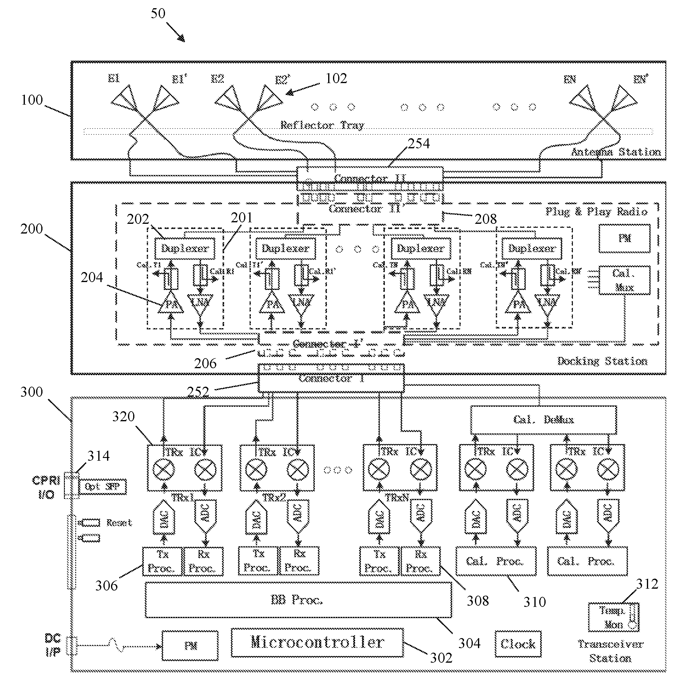
[0028]Turning to the drawings, FIG. 3A shows an active antenna system AAS 50 of the present invention. The active antenna system 50 includes an antenna layer 100, a first electrical component comprising a plug-and-play radio module 200 (PAPR), and a second electrical component comprising a transceiver station or controller 300. The antenna layer 100 includes one or more radiating elements 102 for trans


PUM


Abstract

An ultra wideband active antenna platform can be deployed globally. A plug-and-play radio unit is removably attached to an outside of the active antenna. The PAPR can be removably plugged into a docking station to provide different technology or frequency bands specific for customers in different regions without the costly replacement of the whole antenna.
In addition, the heat-generating sources (power amplifiers) with heavy heatsink structures are separated from the main antenna body, so that the whole active antenna can be installed separately since the installation weight of the antenna would be reduced.

Description


Claims


Application Information

Patent Timeline
Owner AMPHENOL ANTENNA SOLUTIONS
Why Eureka
Try Eureka