Shutter unit, lithography apparatus, and method of manufacturing article

a lithography apparatus and shutter unit technology, applied in the direction of microlithography exposure apparatus, photomechanical treatment, instruments, etc., can solve the problems of unsatisfactory light shielding and undesirable exposure to ligh

Active Publication Date: 2017-09-07
CANON KK
View PDF1 Cites 3 Cited by
  • Summary
  • Abstract
  • Description
  • Claims
  • Application Information

AI Technical Summary

Benefits of technology

The purpose of this new design was that it could be used on certain types of equipment such as Lithographic Apparatuses (LAS). It resulted in better protection from glare caused by sunlight during use compared with previous designs without any modifications or improvements made at all.

Problems solved by technology

The technical problem addressed in this patented technology relates to improving how fast or slow down when changing from one mode (shutdown) to another during printing multiple layers of images onto a wafer for improved efficiency while minimizing unwanted exposures caused by gaps where different parts of the image cannot fully shelter any light falling through due to reflection repeatedly overlapping them.

Method used


Image

  • Shutter unit, lithography apparatus, and method of manufacturing article
  • Shutter unit, lithography apparatus, and method of manufacturing article
  • Shutter unit, lithography apparatus, and method of manufacturing article

Examples


Embodiment Construction

[0014]Various exemplary embodiments, features, and aspects of the invention will be described in detail below with reference to the drawings.

[0015]Embodiments of the present invention will be described in detail below with reference to the accompanying drawings. Note that the present invention is not limited to the following embodiments, and these embodiments are merely practical examples advantageous when carrying out the present invention. In addition, not all the combinations of features described in the embodiments are essential to the solving means of the present invention.

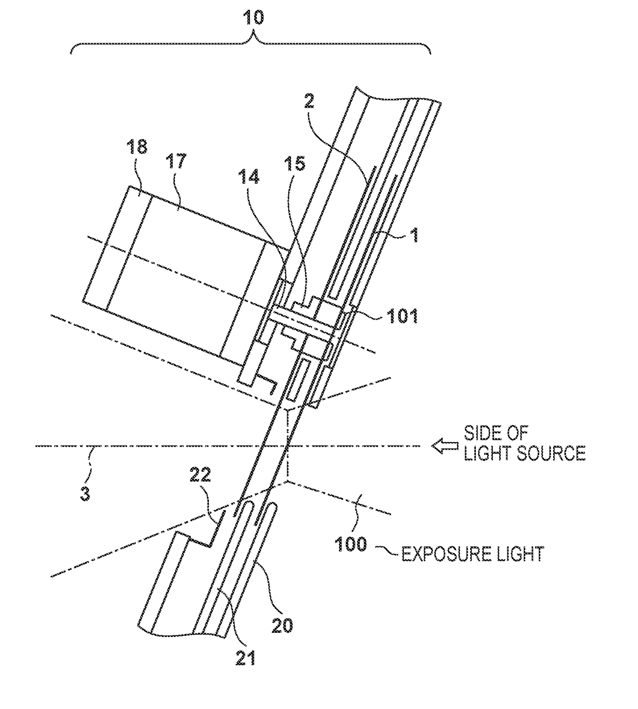
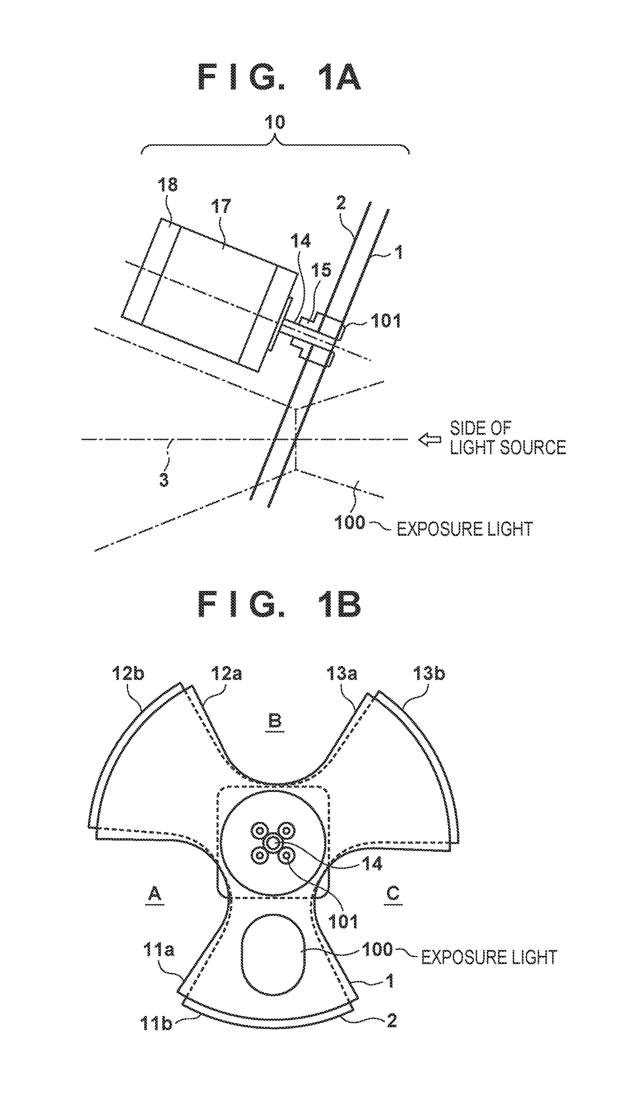
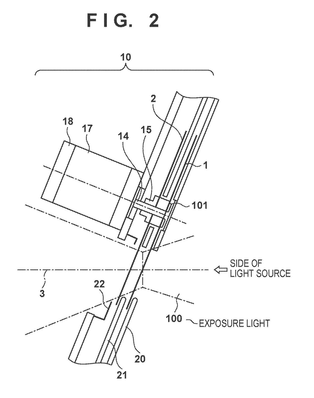
[0016]FIG. 1A is a side view of a shutter unit 10 according to the embodiment, and FIG. 1B is a front view of shutter members of the shutter unit 10 viewed from the side of a light source. The shutter unit 10 is a shutter unit that opens and closes the optical path of an exposure light for a lithography apparatus. The shutter unit 10 can include shutter members that open and close the optical path 3 by rotating


PUM


Abstract

A shutter unit that opens and closes an optical path of light for a lithography apparatus is provided. The shutter unit includes a motor which rotatably drives a shaft extended along a rotation axis of the motor, and a plurality of shutter members attached to the shaft, each including a light shielding portion and a light transmissive portion. The shutter unit further includes a partition plate arranged at a location between the shutter members to avoid a portion through which a light beam passes and configured to shield light that has leaked from a front stage shutter member.

Description


Claims


Application Information

Patent Timeline
Owner CANON KK
Why Eureka
Try Eureka