Additively manufactured composite heater

Active Publication Date: 2018-08-16
CONTINUOUS COMPOSITES INC
View PDF0 Cites 6 Cited by
  • Summary
  • Abstract
  • Description
  • Claims
  • Application Information

AI Technical Summary

Benefits of technology

[0007]In one aspect, the present disclosure is directed to a heating element. The heating element may include a matrix material, and an electrically and thermally conductive fiber that is at least partially encased in the matrix material. The heating element may also include an electrically conductive fiber that extends into the matrix material and connects with the electrically and thermally conductive fiber. A resistance of the electrically and thermally conductive fiber may be higher than a resistance of the electrically conductive fiber.
[0008]In

Problems solved by technology

The resistive nature of the circuit causes the circuit to heat up during transmission of the current.
Although suitable for many applications, conventional electric heaters can also be problematic.
For example, conventional electric heaters can be bulky, heavy, and difficult to package in a manner that lend

Method used


Image

  • Additively manufactured composite heater
  • Additively manufactured composite heater
  • Additively manufactured composite heater

Examples


Embodiment Construction

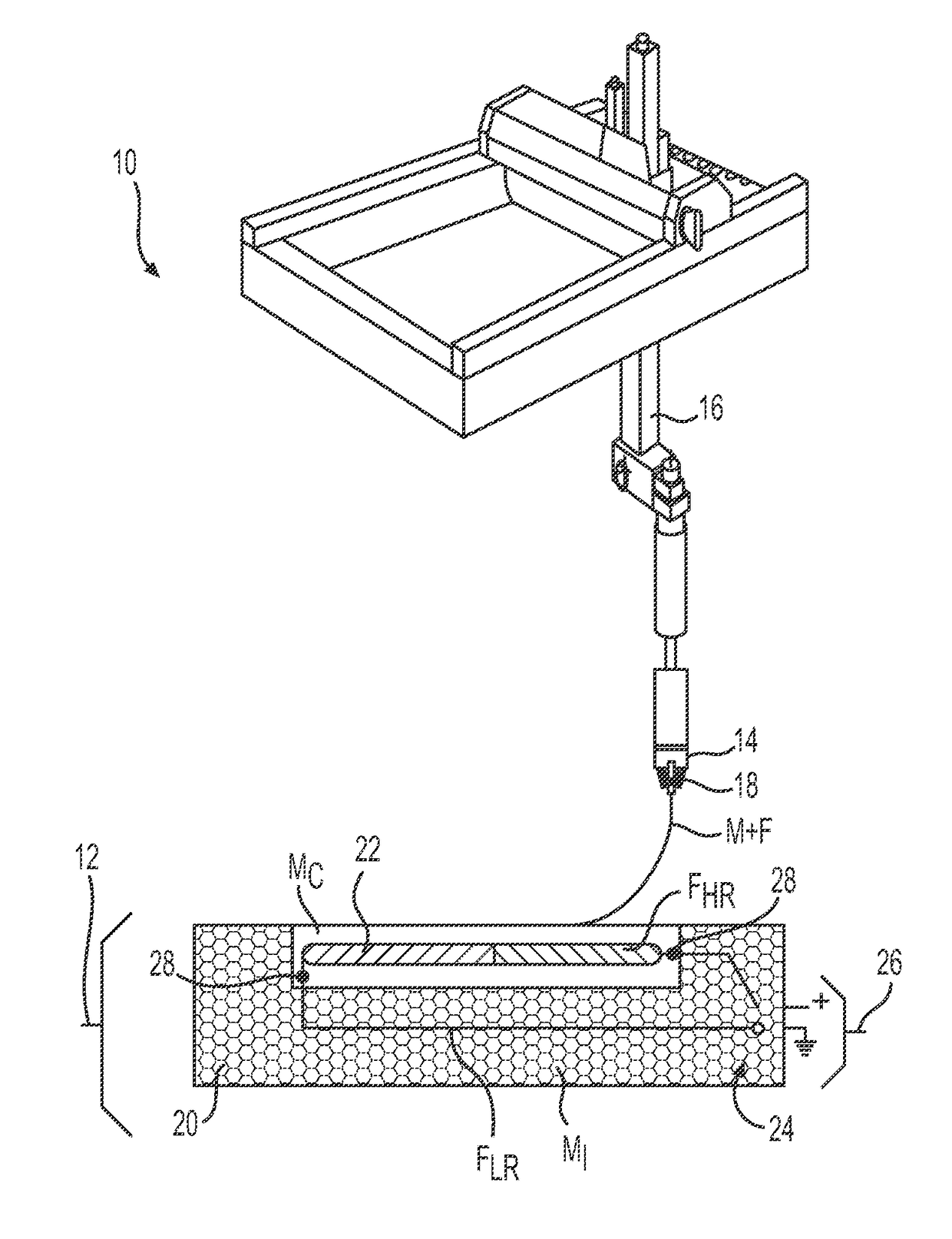
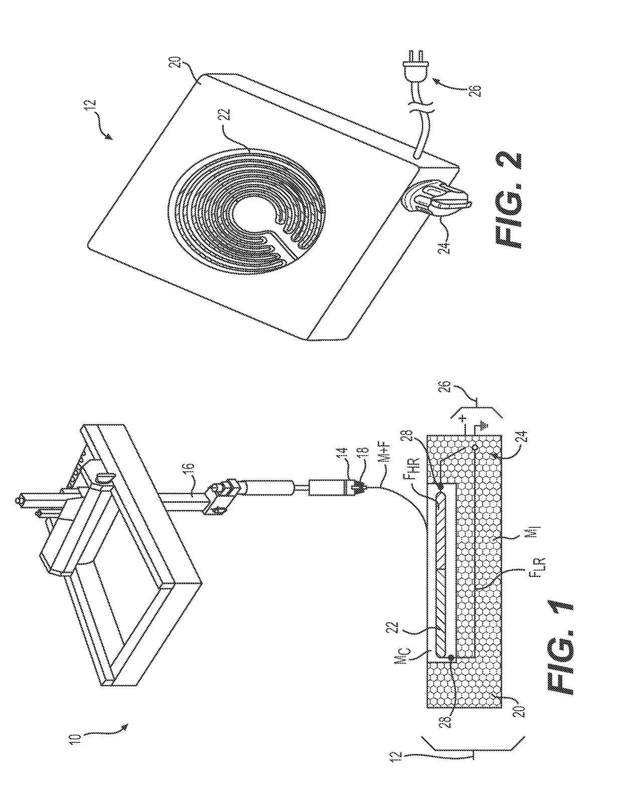
[0012]FIG. 1 illustrates an exemplary system 10 for additively manufacturing a heater 12. System 10 may manufacture heater 12 from a composite material (e.g., a material having a matrix M and at least one continuous fiber F) using a pultrusion and / or extrusion process. System 10 may include one or more heads 14 coupled to a support 16 (e.g., to a robotic arm, to a gantry, to a hybrid gantry-arm, etc.) that is capable of moving head(s) 16 in multiple directions during discharge of the composite material, such that heater 12 is three-dimensional. Such a head is disclosed, for example, in U.S. patent application Ser. Nos. 15 / 130,412 and 15 / 130,207, all of which are incorporated herein in their entireties by reference.

[0013]Head 14 may be configured to receive or otherwise contain the matrix material. The matrix material may include any type of liquid resin (e.g., a zero-volatile organic compound resin) that is curable. Exemplary matrixes include thermosets, single- or multi-part epo


PUM

PropertyMeasurementUnit
Electrical conductoraaaaaaaaaa

Abstract

An composite heater is disclosed. The heater may include a base additively manufactured from a first matrix material, and a heating element additively manufactured adjacent the base from a second matrix material and an electrically and thermally conductive fiber that is at least partially encased in the second matrix material. The heater may also include a control mechanism configured to selectively complete a circuit between a power supply and the electrically and thermally conductive fiber.

Description


Claims


Application Information

Patent Timeline
Owner CONTINUOUS COMPOSITES INC
Why Eureka
Try Eureka