Field-effect transistor without punch-through stopper and fabrication method thereof
a field-effect transistor and punch-through stopper technology, applied in the field of field-effect transistors, can solve the problems of degrading the performance and reliability of the cells of the field-effect transistor, affecting the overall process, and increasing power consumption, so as to achieve high productivity and yield, reduce the effect of reliability degradation
- Summary
- Abstract
- Description
- Claims
- Application Information
AI Technical Summary
Benefits of technology
Problems solved by technology
Method used
Image
Examples
first embodiment
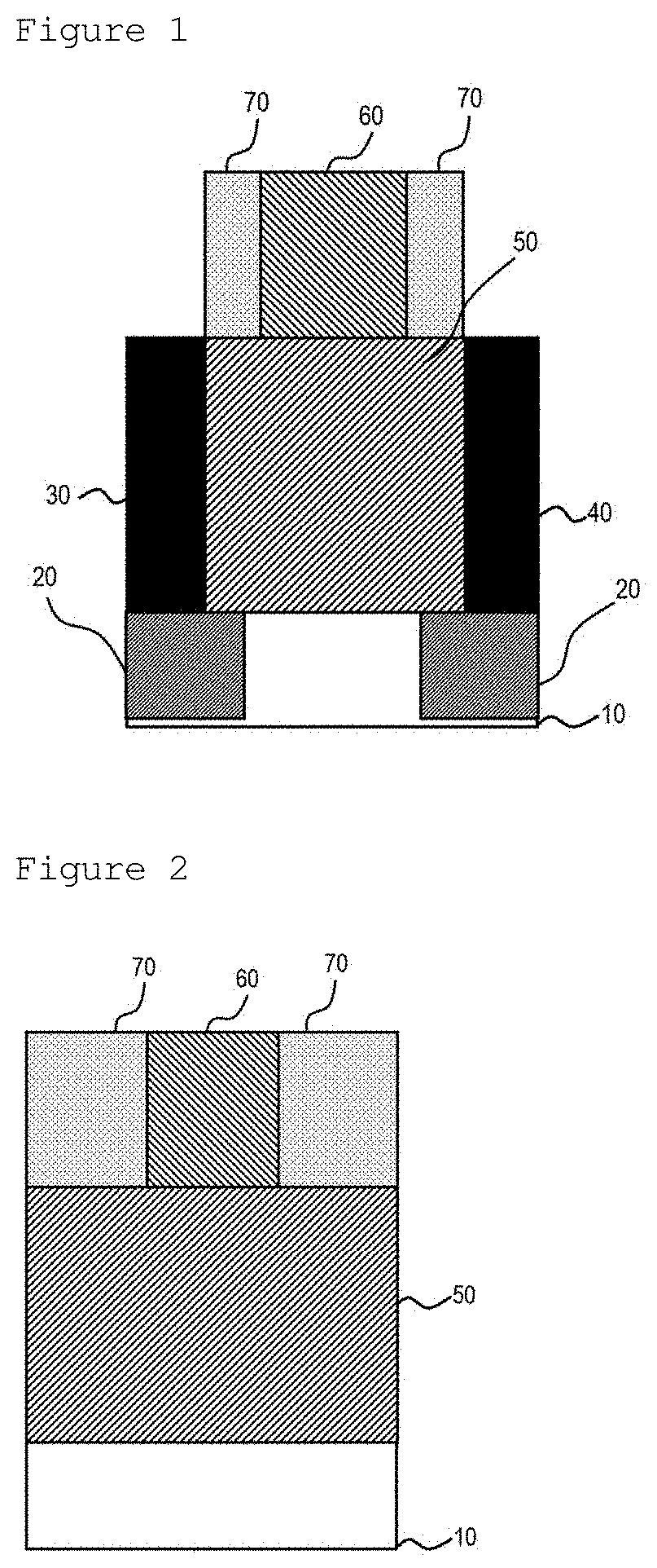
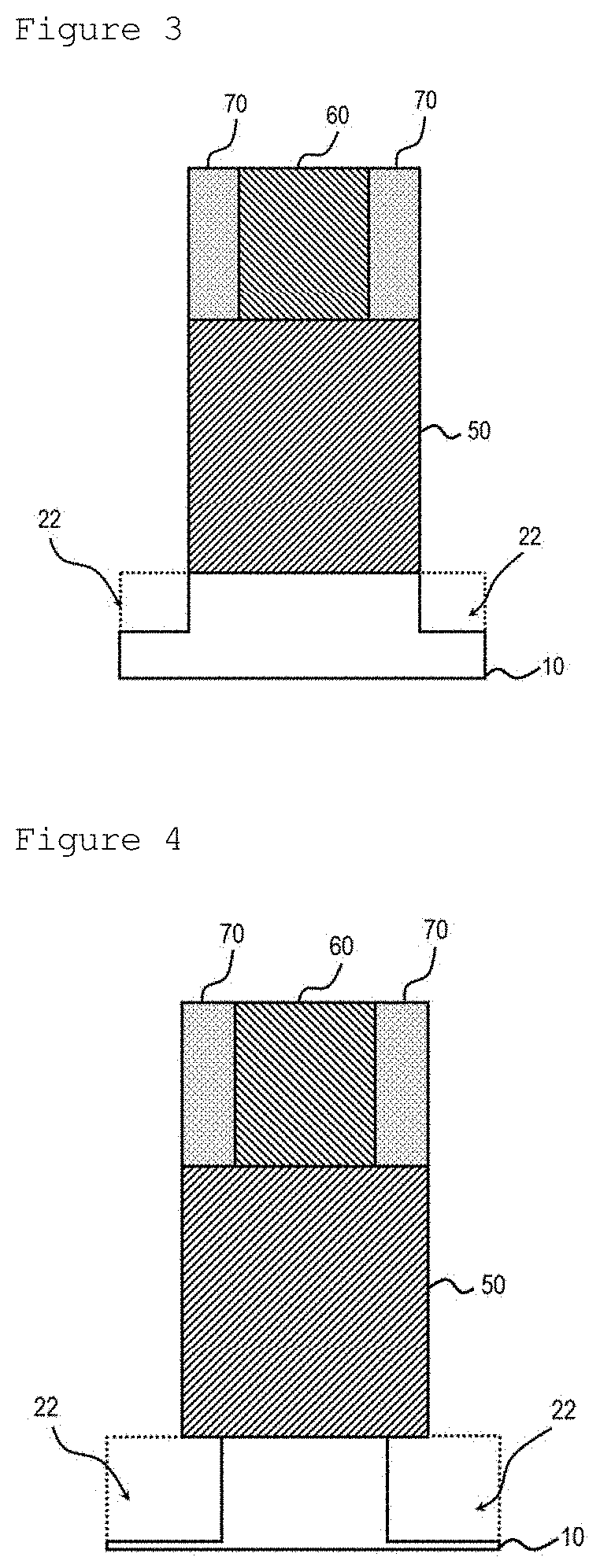
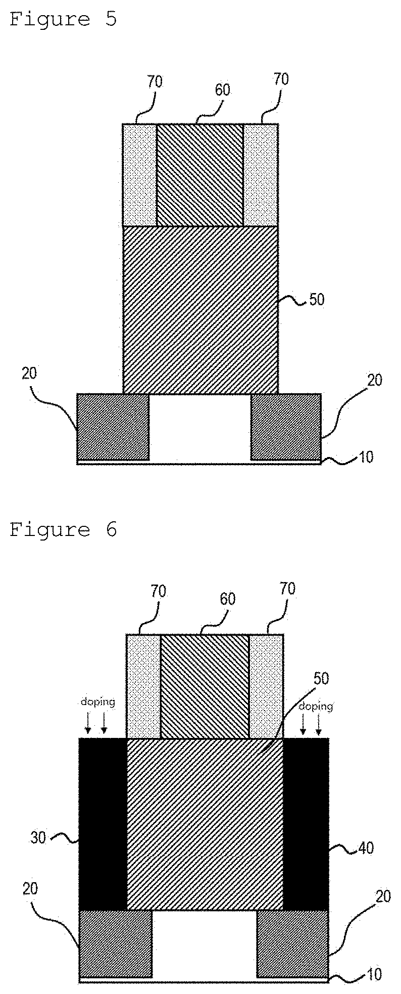
[0029]FIG. 1 is a cross-sectional view of a field effect transistor according to the present disclosure. Specifically, the field effect transistor basically has the same structure as a metal oxide semiconductor field effect transistor (MOSFET).
[0030]Referring to FIG. 1, the field effect transistor includes a substrate 10, a first insulating film 20, Source and drain regions 30 and 40, a channel 50, a gate 60, and a second insulating film 70.
[0031]A conventional field effect transistor has a structure in which a punch-through stopper is formed under the channel. However, in the structure of the field effect transistor according to the present invention, the first insulating film is formed in an upper portion of the substrate 10 to replace the punch-through stopper.
[0032]Specifically, the first insulating film 20 is embedded in the substrate 10, and the source and drain regions 30 and 40 are formed on the first insulating film 20. The first insulating film 20 is partially in contact with
second embodiment
[0065]FIG. 8 is a cross-sectional view illustrating a nanosheet field effect transistor (NSFET), as one exemplary FET structure, according to the present invention. The structure of the NSFET shown in FIG. 8 is illustrated as a single stack in which nanosheets are stacked in three layers for convenience. However, the field effect transistor (FET) according to the present invention may have a multilayer single stack structure in which n or more layers are stacked. Alternatively, the field effect transistor may have a multilayer multi-stack structure including n or more stacks each stack being composed of n or more layers.
[0066]Referring to FIG. 8, the field effect transistor includes a substrate 110, first insulating films 120 partially embedded in an upper portion of the substrate 110, a source region 130 and a drain region 140 respectively positioned on the first insulating films 120, a plurality of horizontally extending channels 150 and a plurality of spacings 180 alternatively arra
PUM
 Abstract
Description
Claims
Application Information
 - R&D Engineer
- R&D Manager
- IP Professional
- Industry Leading Data Capabilities
- Powerful AI technology
- Patent DNA Extraction
Browse by: Latest US Patents, China's latest patents, Technical Efficacy Thesaurus, Application Domain, Technology Topic.
© 2024 PatSnap. All rights reserved.Legal|Privacy policy|Modern Slavery Act Transparency Statement|Sitemap


