Integrated electronic component

a technology of electronic components and components, applied in the direction of electrical apparatus construction details, electrical apparatus casings/cabinets/drawers, semiconductor/solid-state device details, etc., can solve the problems of chip or cracks on the corners, easy damage,

Active Publication Date: 2006-10-24
MURATA MFG CO LTD
View PDF6 Cites 7 Cited by
  • Summary
  • Abstract
  • Description
  • Claims
  • Application Information

AI Technical Summary

Benefits of technology

The technical effect of this patented invention is that it provides an improved way to protect the ceramic material from damage caused during handling or transportation.

Problems solved by technology

This patent describes an integrated electronic component that includes circuit elements mounted on one layer of ceramics called a base plate. However, when it comes into contact with external forces like measuring electrical properties or attaching products onto a wired board, there can occur damage at certain points where the corner between two layers becomes weakened.

Method used


Image

  • Integrated electronic component
  • Integrated electronic component
  • Integrated electronic component

Examples


second preferred embodiment (

FIG. 4.)

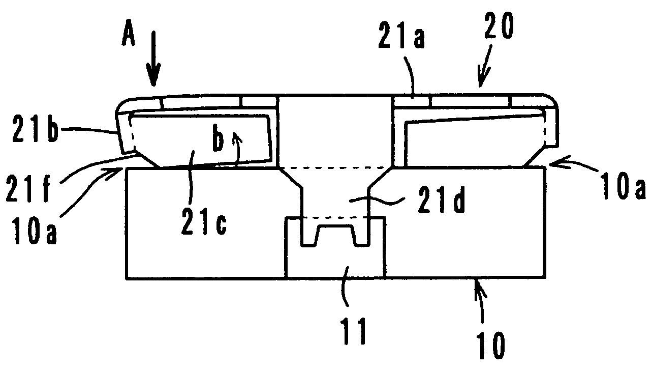
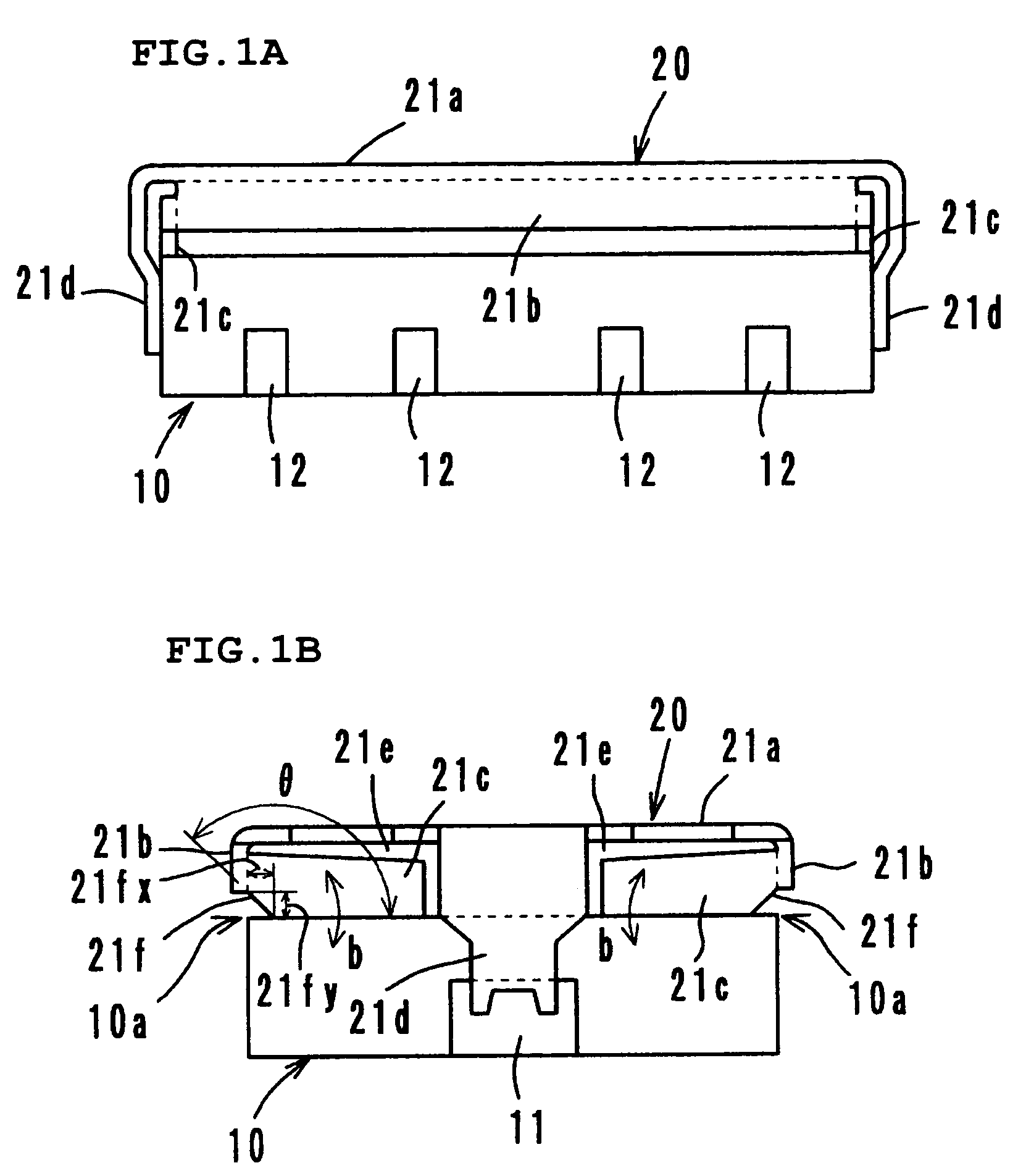
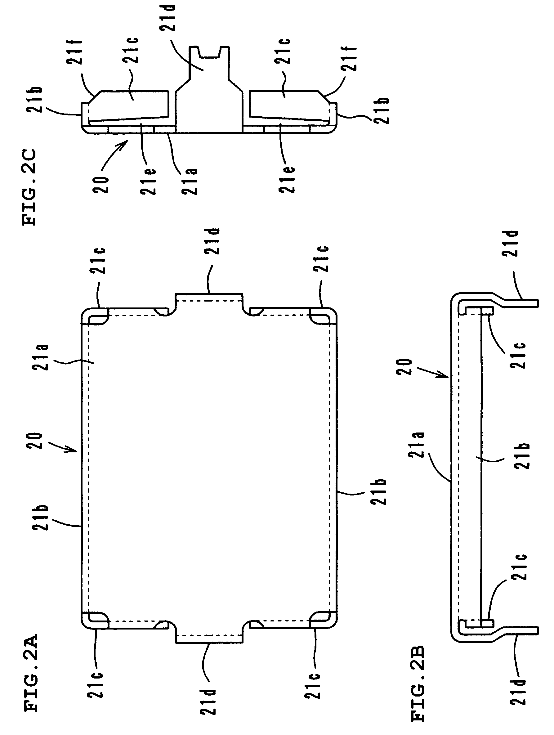
[0032]With reference to FIG. 4, in an integrated electronic component according to a second preferred embodiment, the substrate-facing segments 21c of the metal case 20 have notches 21f preferably having a substantially convex circular arc shape facing downward at the positions opposing the corners 10a of the top surface of the ceramic substrate 10. Other elements are identical to those in the above-described first preferred embodiment. The same reference numerals are used in FIG. 4 and FIGS. 1 to 3 to identify the same elements and blocks, and duplicated descriptions are omitted.

[0033]Herein, a radius of curvature R of the notches 21f′ is preferably about 0.05 mm to about 0.2 mm, for example, about 0.1 mm. If the radius of curvature R is smaller than about 0.05 mm, the substantially circular arc portion of the notches 21f′ easily comes into contact with the corner 10a even if the deformation of the substrate-facing segments 21c is small. This reduces the desirable effect. On t


PUM


Abstract

An integrated electronic component includes a ceramic substrate incorporating circuit elements and/or having circuit elements mounted thereon, and a metal case mounted on the ceramic substrate. Notches are formed in substrate-facing segments of the metal case at the positions opposing the corners of the top surface of the ceramic substrate. The notches have a tapered shape having obtuse angles with respect to the top surface of the substrate. The notches may have a substantially circular arc shape. The substrate-facing segments having the notches are seamlessly connected to side segments of the metal case, bent in the vicinity of the notches, and supported by the bent portions in a cantilevered fashion.

Description


Claims


Application Information

Patent Timeline
Owner MURATA MFG CO LTD
Why Eureka
Try Eureka