Manufacture of RFID tags and intermediate products therefor

a technology of radio frequency identification and intermediate products, which is applied in the direction of casings/cabinets/drawers, instruments, casings/cabinets/drawers, etc., can solve problems such as mechanical connections failing, and achieve the effect of facilitating manufacture and high effectiveness

Inactive Publication Date: 2007-06-12
A K STAMPING
View PDF6 Cites 9 Cited by
  • Summary
  • Abstract
  • Description
  • Claims
  • Application Information

AI Technical Summary

Benefits of technology

The technical effect of this patented technology improves the production process and product quality by making it easier to manage large amounts of items that are being shipped or stored on-site. This helps companies make better decisions about how to purchase these items more efficiently.

Problems solved by technology

The technical problem addressed in this patent text is how to create a more affordable and easily-produced RFID tag without requiring expensive materials or complicated process steps.

Method used


Image

  • Manufacture of RFID tags and intermediate products therefor
  • Manufacture of RFID tags and intermediate products therefor
  • Manufacture of RFID tags and intermediate products therefor

Examples


Embodiment Construction

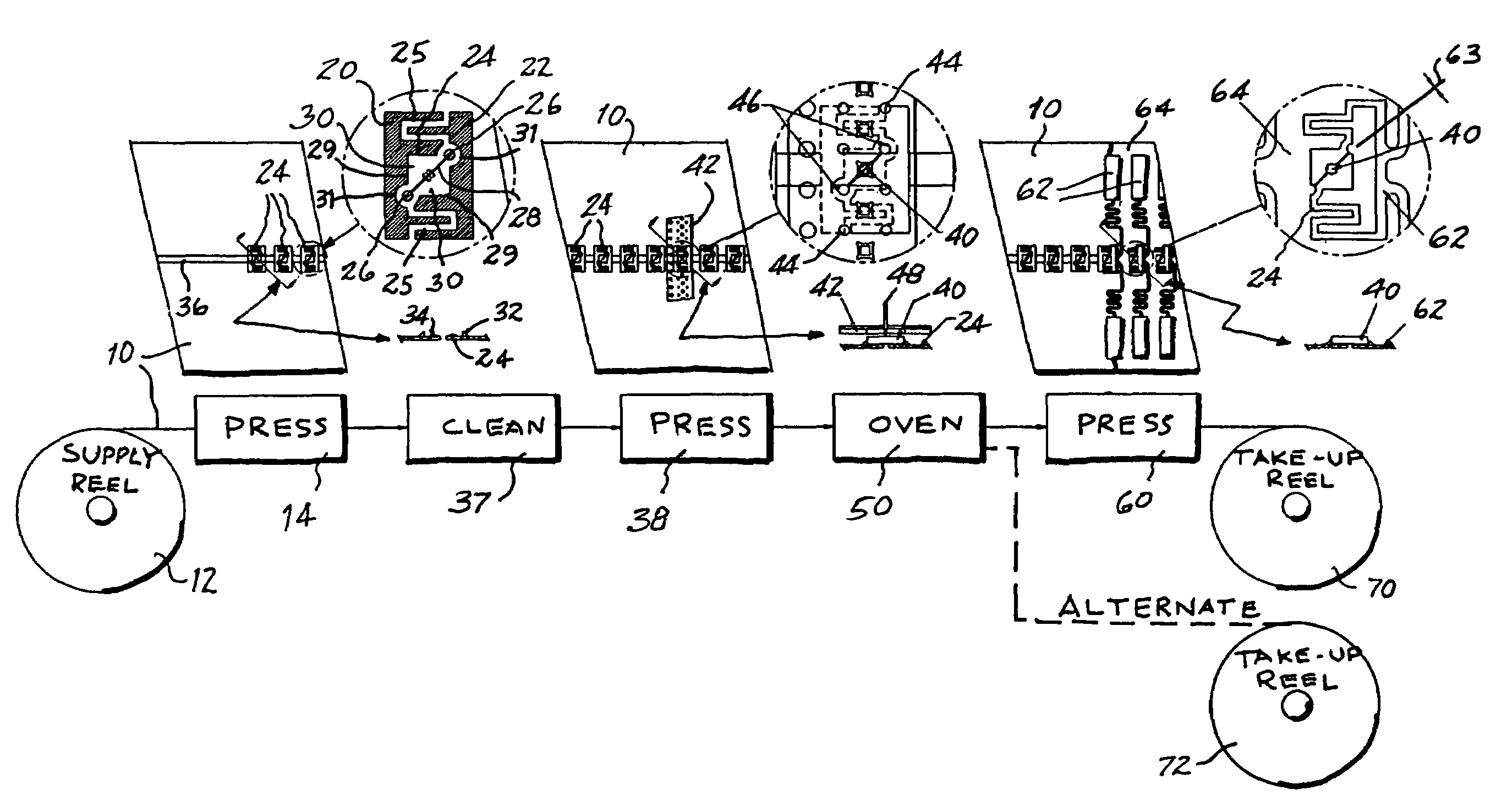
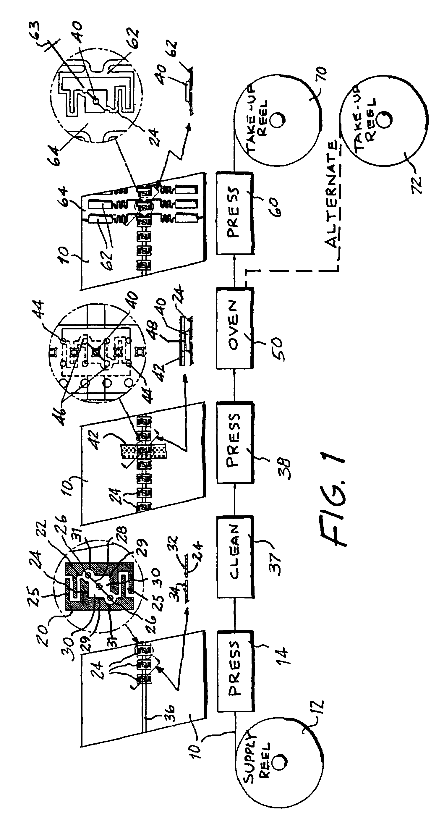
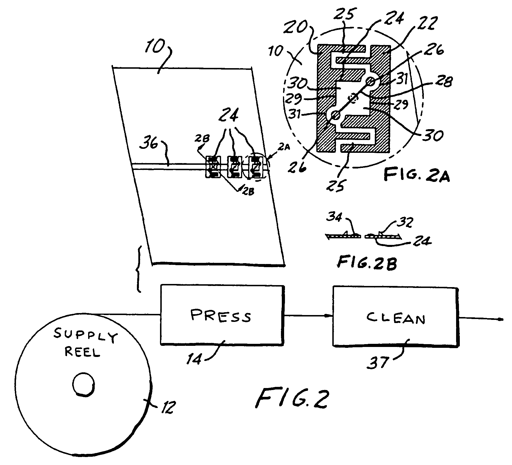
[0029]Referring now to the drawing, and especially to FIG. 1 thereof, a sequential line is illustrated in which an aluminum strip 10 is supplied from a supply reel 12 and advanced along a longitudinal direction to a first press 14 where portions of the strip 10 are punched from the strip 10, as represented by shaded areas 20 and 22, to establish a series of contact members 24 integrated with and carried by the remainder of the strip 10, spaced longitudinally from one another along the strip 10, each contact member 24 remaining coupled with the strip 10 by a compliant coupling arrangement shown in the form of undulant arms 25 connecting each contact member 24 with the strip 10.

[0030]Locators in the form of pilot holes 26 are placed at the opposite ends of a slot 28 which separates each contact member 24 into two contact elements 29 such that the overall area of each contact member 24 is divided into two separate contact areas 30. The pilot holes 26 extend altitudinally through ears 31 f


PUM

PropertyMeasurementUnit
Lengthaaaaaaaaaa
Electrical conductivityaaaaaaaaaa
Areaaaaaaaaaaa

Abstract

In the manufacture of RFID tags, electronic components are connected with soldered connections to antennas stamped from a thin strip of electrically conductive metal, utilizing methods and intermediate products which enable accurate registration of the leads of the electronic components with contacts on the antennas. Thus, a strip of metal is provided with contact members unitary with the strip and coupled to the strip through compliant coupling arrangements which allow compliant movement of the contact members relative to the strip for accurate alignment with electronic components juxtaposed with the contact members for soldered connections between the leads of the electronic components and the corresponding contact members. The antennas, with the electronic components soldered in place, are carried by a substrate, and the sequence of the stamping and soldering operations avoids exposing the substrate to the heat of soldering.

Description


Claims


Application Information

Patent Timeline
Owner A K STAMPING
Why Eureka
Try Eureka