Laser welding apparatus and method of laser welding
A laser welding and laser beam technology, applied in laser welding equipment, welding/welding/cutting items, auxiliary devices, etc., can solve problems such as difficult handling, deformation of copper plates, difficulty in evenly pushing backing flux and copper plates on welding lines, etc. , to achieve the effect of preventing quality reduction and inhibiting melting
- Summary
- Abstract
- Description
- Claims
- Application Information
AI Technical Summary
Benefits of technology
Problems solved by technology
Method used
Image

Examples
no. 1 approach
[0077] Below, refer to Figure 1~Figure 8 The back wave holding device used for laser welding in the first embodiment of the present invention will be described.
[0078] figure 1 It is a schematic diagram explaining the structure of the back wave holding device of this embodiment.
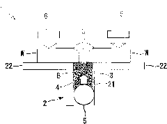
[0079] The back wave holding device (laser welding device) 1 of the present embodiment is used to maintain the back wave B when laser welding a welding target W that is a large structure such as a ship. E.g figure 1 As shown, it is used when welding a welding object W having a gap G.
[0080] Such as figure 1 As shown, the back wave holding device 1 is provided with a frame body 2, flux 3, sand (supporting part) 4, and hose (pressing part) 5.
[0081] Such as figure 1 As shown, the frame body 2 supports the flux 3, the bottom sand 4, and the hose 5, and is arranged to be in contact with the welding target W during welding.
[0082] The frame 2 is provided with a gap G (relative to the figure 1 The groove 21 e
no. 2 Embodiment approach
[0142] Below, refer to Figure 9 ~ Figure 12 The second embodiment of the present invention will be described.
[0143] The basic structure of the back wave holding device of this embodiment is the same as that of the first embodiment, but is different from that of the first embodiment in the vicinity of the flux layer. In this embodiment, use Figure 9 ~ Figure 12 Only the structure around the flux will be described, and descriptions of other components and the like will be omitted.
[0144] Picture 9 It is a schematic diagram explaining the structure of the back wave holding device of this embodiment. Picture 10 Is description Picture 9 Schematic diagram of the placement of the gasket.
[0145] In addition, the same reference numerals are given to the same constituent elements as those of the first embodiment, and the description thereof is omitted.
[0146] Such as Picture 9 and Picture 10 As shown, the back wave holding device 101 is provided with a frame body 2, a flux 3, a san
no. 3 approach
[0156] Refer below Figure 13 ~ Figure 15 The third embodiment of the present invention will be described.
[0157] The basic structure of the back wave holding device of this embodiment is the same as that of the first embodiment, but the structure between the flux and the hose is different from that of the first embodiment. Therefore, in this embodiment, use Figure 13 ~ Figure 15 Only the structure between the flux and the hose will be described, and the description of other structural elements and the like will be omitted.
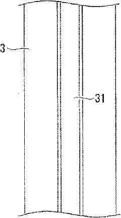
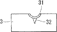
[0158] Figure 13 It is a schematic diagram explaining the structure of the back wave holding device of this embodiment.
[0159] In addition, the same reference numerals are given to the same constituent elements as those of the first embodiment, and the description thereof is omitted.
[0160] Such as Figure 13 As shown, the back wave holding device 201 is provided with a frame body 2, a flux 3, a sand 4, a hose 5, and a thin metal plate (shielding portion)
PUM
 Abstract
Description
Claims
Application Information
 - R&D Engineer
- R&D Manager
- IP Professional
- Industry Leading Data Capabilities
- Powerful AI technology
- Patent DNA Extraction
Browse by: Latest US Patents, China's latest patents, Technical Efficacy Thesaurus, Application Domain, Technology Topic.
© 2024 PatSnap. All rights reserved.Legal|Privacy policy|Modern Slavery Act Transparency Statement|Sitemap