Lithium ion battery pack and soldering method for single batteries therein

A technology for lithium-ion battery packs and single cells, which is applied to battery pack components, welding equipment, non-aqueous electrolyte batteries, etc. Avoid the effect of bloating

Active Publication Date: 2012-01-25
SHENZHEN GREPOW BATTERY CO LTD
View PDF3 Cites 16 Cited by
  • Summary
  • Abstract
  • Description
  • Claims
  • Application Information

AI Technical Summary

Benefits of technology

Inventions described by this patented technology are used during manufacturing processes on batteries with multiple individual cell units joined together through specific techniques such as soldering. By doing these steps, it prevents excessive temperatures within each unit's internal components caused by direct contact when they come into physical contact. Additionally, there is also an air space around them where some parts of the energy produced by one component may escape while others continue working properly. Overall, this technique helps improve safety performance over traditional methods like create better quality batteries without causing damage.

Problems solved by technology

This patented technical problem addressed by this patents relates to improving upon existing methods used when connecting different types of electronic components such as batteries (lithium ion), nickels/nickel hydrogen bags, alkaline storage batteries like sodium sulfur batteries) without losing their ability to provide sufficient power during use.

Method used


Image

  • Lithium ion battery pack and soldering method for single batteries therein
  • Lithium ion battery pack and soldering method for single batteries therein
  • Lithium ion battery pack and soldering method for single batteries therein

Examples


Embodiment 1

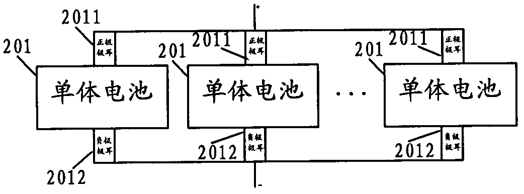
[0052] The lithium-ion battery pack provided in this embodiment is composed of a plurality of single cells. Each single cell can be as figure 2 The lithium-ion battery pack is formed by connecting in parallel with each other as shown: the positive tabs 2011 and the positive tabs 2011 of any two single batteries 201 are welded to each other, and the negative tabs 2012 and 2012 are welded to each other. Finally: the positive tabs 2011 of all single cells 201 serve as the positive poles of the lithium-ion battery pack, and the negative tabs 2012 of all single cells 201 serve as the negative poles of the lithium-ion battery pack to provide external power supply.

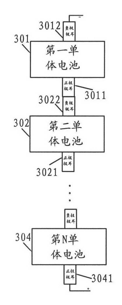
[0053] Each single battery can also be as image 3 The lithium-ion battery pack is formed in series with each other as shown: the positive pole tab 3011 of the first unit battery 301 is welded to the negative pole tab 3022 of the second unit battery 302, and the positive pole tab 3021 of the second unit battery 302 is con

Embodiment 2

[0069] Similar to Embodiment 1, the lithium-ion battery pack provided in this embodiment is composed of a plurality of single cells. Each single cell can be as figure 2 The lithium-ion battery packs shown are connected in parallel with each other. Each single cell can also be as image 3 The lithium-ion batteries shown are connected in series with each other.

[0070] In the lithium-ion battery pack of this embodiment, no matter whether it adopts a plurality of single cells connected in parallel or in series, the welding structure of any two interconnected tabs of any two single cells is as follows: Figure 4 shown.

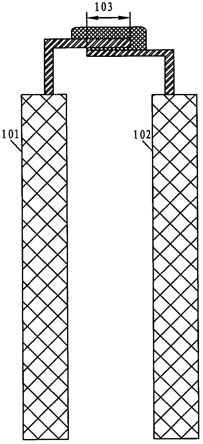
[0071] The two mutually welded tabs of any two single cells are recorded as the first tab 4011 and the second tab 4021. The welding connection method of the first tab 4011 and the second tab 4021 mainly includes the following steps:

[0072] Step 501 : Pad a rigid plate 404 on the back of the horizontally bent sections of the first tab 4011 and the second tab 4


PUM


Abstract

The invention relates to the field of lithium ion battery designs, and discloses a lithium ion battery pack and a soldering method for single batteries therein. The lithium ion battery pack comprises a plurality of single batteries which are connected in series or in parallel through soldered lugs; and the soldering method for soldering the first lug and the second lug of any two single batteries includes the following steps: a rigid plate is arranged on the backs of the horizontal bent sections of the first lug and the second lug, and is in plane contact with the backs of both the first lug and the second lug, wherein a predetermined gap is reserved between the first lug and the second lug which are horizontally opposite to each other; soldering is carried out on the top of the rigid plate in the gap between the first lug and the second lug, a tin bar is melted, the gap is covered by and filled with the melted tin, and the melted tin permeates to the top of the rigid plate; and the melted tin is solidified and shaped. The heat-dissipating effect of the method is better, and moreover, the structure of the soldered parts of the lugs is firmer, which can help to enhance the conductivity of the lithium ion battery pack.

Description


Claims


Application Information

Patent Timeline
Owner SHENZHEN GREPOW BATTERY CO LTD
Why Eureka
Try Eureka