Residual heat absorbing boiler for CO

A boiler and waste heat technology, which is applied in the field of refractory layer boilers, can solve the problems that the exhaust gas cannot be evenly distributed, the CO is difficult to be fully burned, and the CO is fully burned, so as to achieve the effect of convenient and full combustion, complete combustion of exhaust gas, and increased combustion time.

Inactive Publication Date: 2012-10-17
无锡市晨光耐火材料有限公司
View PDF5 Cites 0 Cited by
  • Summary
  • Abstract
  • Description
  • Claims
  • Application Information

AI Technical Summary

Benefits of technology

This new carbon-fiber composite material (CFC) used for reducing harmful emissions from fossil fuel fired power plants was developed during this patented process compared to previous methods that had problems such as high maintenance costs or environmental concerns associated therewith. These technical improvements resulted in improved efficiency and reduced airborne particulate matter levels.

Problems solved by technology

This patented technical problem addressed by this patents relates to improving the efficiency of burning fossil fuels with low emissions without generating excessive amounts of harmful wastes or producing valuable products from them.

Method used


Image

  • Residual heat absorbing boiler for CO

Examples


Embodiment Construction

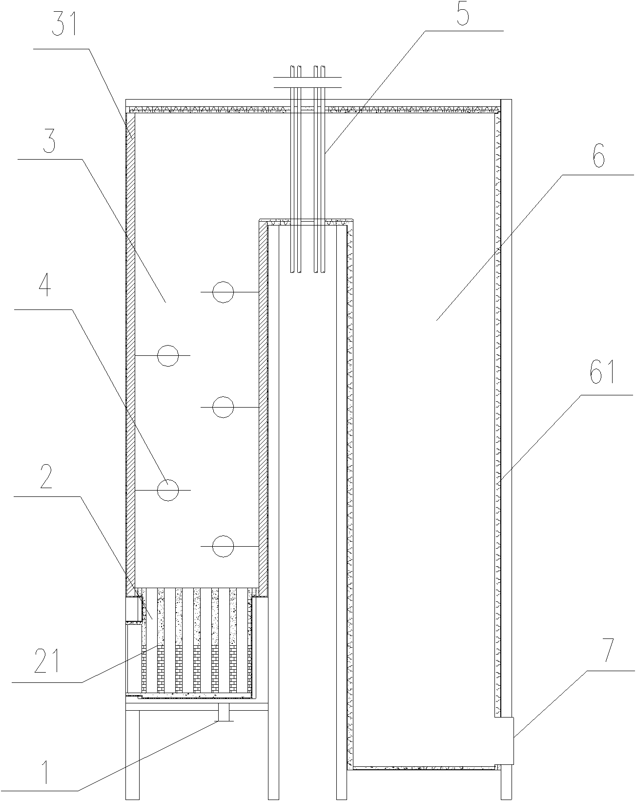
[0017] As shown in the figure, a CO waste heat absorption boiler provided by the present invention includes an inlet 1, a flue gas mixing chamber 2, a combustion chamber 3, a burner 4, a wall pipe 5, an evaporation chamber 6 and an outlet 7; the flue gas mixing chamber 2 is located above the entrance 1 and below the combustion chamber 3, and a grille 21 is provided in the flue gas mixing chamber 2 to make the flue gas mix uniformly and buffer the flow velocity of the flue gas; the combustion chamber 3 is equipped with 5 burners 4, crossed Distributed in the combustion chamber 3; in order to prevent high temperature, the side wall 31 of the combustion chamber is made of high-alumina lightweight bricks; there is a wall-through pipe 5 between the combustion chamber 4 and the evaporation chamber 6 to absorb the heat generated by CO combustion; the side wall of the evaporation chamber 61 is filled with refractory materials to facilitate waste heat absorption; the bottom of the evaporat


PUM


Abstract

The invention discloses a residual heat absorbing boiler for CO, comprising an inlet, a combustion chamber, a combustor, an evaporation chamber and an outlet; a smoke mixing chamber is arranged above the inlet and below the combustor. According to the invention, the structure is simple; the design is scientific and reasonable; CO in waste gas is combusted fully, and is discharged so as to greatly increase combustion efficiency, and to be beneficial to residual heat absorption of CO, and no pollution is generated.

Description


Claims


Application Information

Patent Timeline
Owner 无锡市晨光耐火材料有限公司
Why Eureka
Try Eureka