Turbine residual heat recycling and utilizing system

A technology of waste heat recovery and turbine, applied in pipeline system, engine components, machines/engines, etc., can solve the problems of increasing the risk of boiler safe operation, lack of spare boilers, reducing the chance of maintenance of heat medium boilers, etc., to reduce boiler fuel Consumption, improve equipment safety operation coefficient, light weight effect

Inactive Publication Date: 2012-10-31
CHINA NAT OFFSHORE OIL CORP +1
View PDF5 Cites 3 Cited by
  • Summary
  • Abstract
  • Description
  • Claims
  • Application Information

AI Technical Summary

Problems solved by technology

In order to ensure the quality of crude oil exported, two heat medium boilers must be put into operation at the same time to increase the capacity of processing liquid. In this

Method used


Image

  • Turbine residual heat recycling and utilizing system

Examples


Example Embodiment

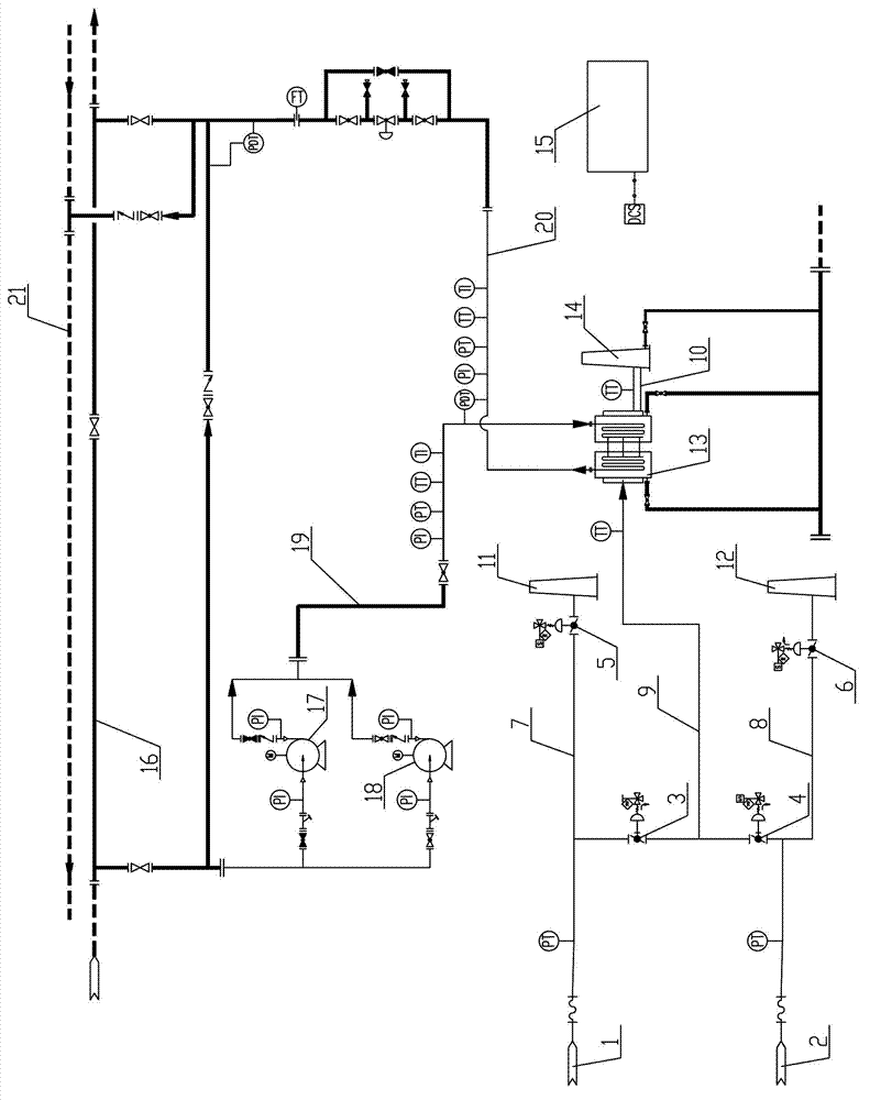
[0032] In order to further understand the content, features and effects of the present invention, the following describes the turbine waste heat recovery system of the present invention in detail:

[0033] As shown in the figure, this embodiment discloses a turbine waste heat recovery and utilization system, which uses the high-temperature flue gas discharged from the turbine as the heat source, recovers the flue gas waste heat, and uses the high-temperature flue gas to heat the waste heat furnace 13 The heat transfer oil in the heat exchange coil is heated to maximize the recovery and utilization of the waste heat of the turbine unit and realize energy saving and emission reduction. It is mainly composed of waste heat furnace 13, hot oil circulation pump, flue gas valve and on-site control panel 15, etc. Equipment composition.

[0034] The heat load of the waste heat furnace 13 in this embodiment is 3000KW, the design pressure is 1.2MPa, the maximum working pressure is 0.9MPa, the de


PUM


Abstract

The invention discloses a turbine residual heat recycling and utilizing system which mainly comprises a residual heat boiler, a hot oil circulating pump, a smoke valve and a field control disc. High-temperature smoke discharged by a turbine motor is used as a heat source and the residual heat of smoke is recycled; heat-conducting oil is introduced to a residual heat boiler heat exchanging disc through a hot oil circulating pump and the heat-conducting oil in a residual heat boiler heat exchanging coiled pipe is heated by utilizing the high-temperature smoke; and after the heat-conducting oil is heated, the heat-conducting oil is returned to a heat-conducting oil system. According to the turbine residual heat recycling and utilizing system disclosed by the invention, the heat energy in turbine smoke can be recycled and the heat-conducting oil can be heated by effectively utilizing the residual heat of the smoke, so that the temperature of the heat-conducting oil is improved, the consumption of fuel is reduced, the load of a previous heat medium boiler is reduced, and the normal maintenance of the heat medium boiler and the normal operation of a hot oil system are guaranteed; and therefore, the risk of safely operating the previous heat medium boiler is reduced, the safety operating factor of equipment is improved and the pressure of outputting crude oil is relieved. Meanwhile, the emission of atmospheric pollutants is further reduced, and energy conservation and emission reduction are realized.

Description


Claims


Application Information

Patent Timeline
Owner CHINA NAT OFFSHORE OIL CORP
Why Eureka
Try Eureka