Drill bit of hollow drill and manufacturing method thereof

A hollow drill and drill bit technology, which is applied in drilling/drilling equipment, drill repairing, drilling tool accessories, etc., can solve the problems of poor chip removal, easy wear, and small chip space, and achieve the effect of not being easily deformed

Inactive Publication Date: 2014-04-30
宁波神钻工具有限公司
View PDF6 Cites 10 Cited by
  • Summary
  • Abstract
  • Description
  • Claims
  • Application Information

AI Technical Summary

Benefits of technology

This new type of tool has several benefits compared with older tools that were previously used: it's resistant to rustiness or damage from being left over after use; its strength makes them stronger than previous ones while still maintain their shape when bent around without getting damaged during usage.

Problems solved by technology

This patented technical problem addressed by this patents relates to improving hollow cut tools' performance when processing large circular openings with sharp edges or chips that may be difficult to remove without causing damage.

Method used


Image

  • Drill bit of hollow drill and manufacturing method thereof

Examples


Embodiment Construction

[0025] The present invention will be further described below in conjunction with accompanying drawings and examples.

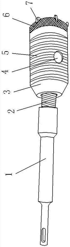
[0026] As shown in the figure, a hollow drill bit includes a drill shank 1 and a cylinder body 3. It is characterized in that: the top end of the cylinder body 1 is provided with a wear-resistant layer 6, and a number of cutting teeth 7 are evenly distributed on the wear-resistant layer 6. , the wear-resistant layer 6 is formed by overlay welding of wear-resistant materials, the cutting teeth 7 are directly welded on the wear-resistant layer 6, the side of the cylinder 3 is provided with chip removal holes 4, and the outer surface of the cylinder 3 is A chip removal groove 5 is provided, the chip removal groove 5 is threaded, the top of the drill shank 1 is provided with an external thread 2, the drill shank 1 is connected with the cylinder 3 through the external thread 2, and the bottom of the cylinder 3 is There are matching internal threads in the mounting hol


PUM

PropertyMeasurementUnit
Thicknessaaaaaaaaaa

Abstract

The invention discloses a drill bit of a hollow drill. The drill bit comprises a drill handle and a barrel, and is characterized in that the top end of the barrel is provided with a wear-resistant layer; a plurality of cutting teeth are uniformly distributed on the wear-resistant layer; the wear-resistant layer is formed by overlaying a JY49-1 material at one time; the cutting teeth are directly welded on the wear-resistant layer. The drill bit has the advantages of corrosion resistance, easiness in cleaning, firmness, prevention of deformation and durability.

Description


Claims


Application Information

Patent Timeline
Owner 宁波神钻工具有限公司
Why Eureka
Try Eureka