Radiation image pick-up device and image processing method
A shooting device and technology of radiation, applied in the field of radiation shooting
- Summary
- Abstract
- Description
- Claims
- Application Information
AI Technical Summary
Problems solved by technology
Method used
Image

Examples
no. 1 approach 》
[0027] Hereinafter, a first embodiment to which the present invention is applied will be described using the drawings. In addition, in the whole drawing for explaining each embodiment, the structure to which the same name and the same code|symbol are attached|subjected has the same function, and the repeated description is abbreviate|omitted.
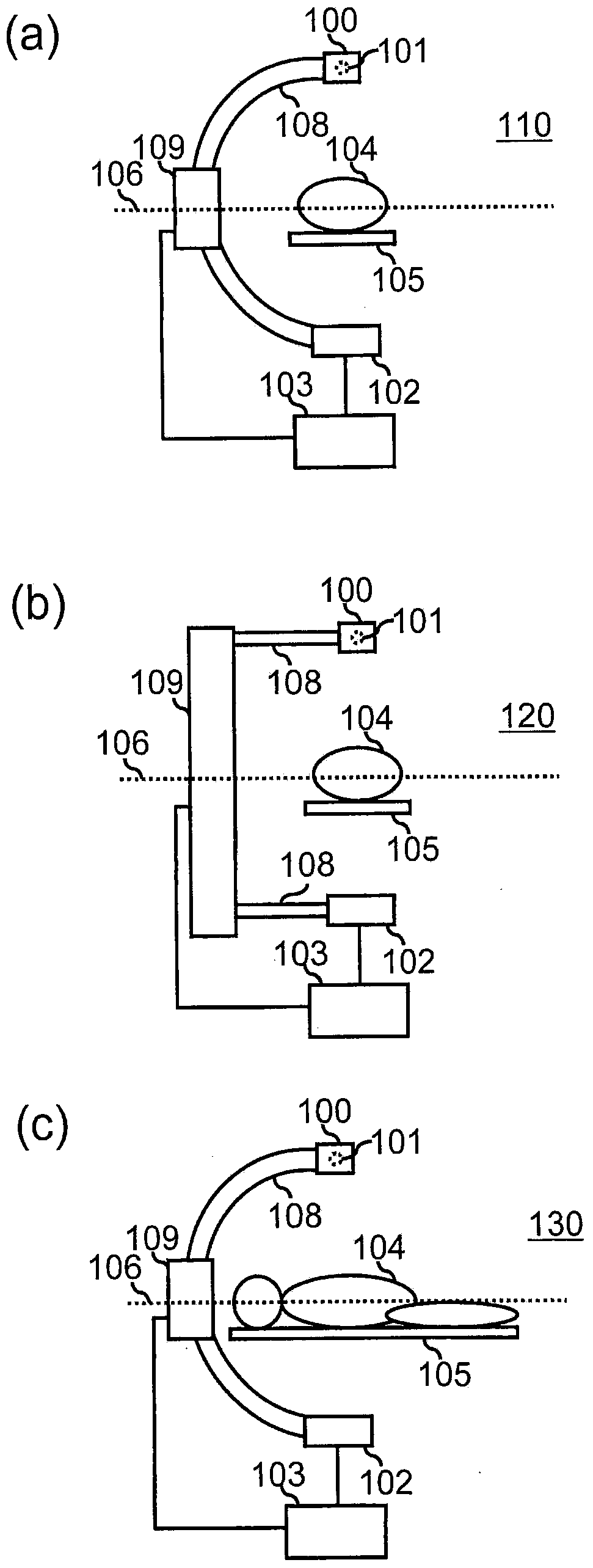
[0028] figure 1 (a)-(c) are schematic views of the X-ray imaging apparatuses 110, 120, and 130 according to this embodiment. The X-ray imaging devices 110, 120, and 130 of this embodiment include: an X-ray tube 100 having an X-ray source 101 for irradiating an X-ray to an object 104, a detector 102 for detecting X-rays, a control device 103, an arm 108, and mobile device 109 . 105 in the figure is a bed on which the subject 104 is placed. An X-ray source 101 and a detector 102 inside the X-ray tube 100 are connected to a moving device 109 via an arm 108 . The control device 103 sends instructions to the moving device 109 to move the X-
no. 2 approach 》
[0087] Next, a second embodiment to which the present invention is applied will be described. In the present embodiment, the weight applied to each rotated measurement image is optimized.
[0088] The X-ray imaging device of this embodiment is the same as that of the first embodiment. That is, one can also use the above figure 1 Any one of (a) to (c). In addition, the functions of each part are basically the same. However, in this embodiment, in order to optimize the weights, the processing of the weight determination unit 322 is different. Hereinafter, this embodiment will mainly describe configurations different from those of the first embodiment.
[0089] Similar to the first embodiment, the weight determination unit 322 of this embodiment determines at least one of the weight value, the size of the smoothing region, and the shape of the reconstruction filter as the weight applied to each measurement angle of each rotated measurement image. At this time, weights are confi
no. 3 approach 》
[0117] Next, a third embodiment to which the present invention is applied will be described. In the present embodiment, measurement is repeatedly performed in a predetermined rotation angle range (unit rotation angle range) smaller than 180 degrees. Within the range of each unit rotation angle, measurement images are continuously obtained according to each predetermined measurement angle. That is, in the present embodiment, measurements corresponding to different rotation angle ranges are performed multiple times to obtain one reconstructed image. In this embodiment, an image is reconstructed for each unit rotation angle range. In addition, weights are determined for each unit rotation angle range by the same method as in the first embodiment. In addition, the unit rotation angle ranges for acquiring the measurement images may not be continuous.
[0118] The X-ray imaging device of this embodiment is basically the same as that of the first embodiment. However, the measurement
PUM
 Abstract
Description
Claims
Application Information
 - R&D Engineer
- R&D Manager
- IP Professional
- Industry Leading Data Capabilities
- Powerful AI technology
- Patent DNA Extraction
Browse by: Latest US Patents, China's latest patents, Technical Efficacy Thesaurus, Application Domain, Technology Topic.
© 2024 PatSnap. All rights reserved.Legal|Privacy policy|Modern Slavery Act Transparency Statement|Sitemap