Connector capable of solving easy upwarping problem and design method thereof

A design method and connector technology, applied in connection, fixed connection, installation of connection parts, etc., can solve problems such as loose connection between connector pins and shells, unstable working state of connectors, and shortened service life of connectors, etc., to achieve Avoid the risk of easy upturning, simple structure, and reduce the risk of use

Inactive Publication Date: 2016-09-21
LANGCHAO ELECTRONIC INFORMATION IND CO LTD
View PDF5 Cites 0 Cited by
  • Summary
  • Abstract
  • Description
  • Claims
  • Application Information

AI Technical Summary

Benefits of technology

This new technology solves problems that were previously difficult or expensive when used alone due to its tendency towards being easily bent over by external forces such as winds during installation. It improves both stability and reliability while reducing costs compared to previous designs.

Problems solved by technology

This patents describes how current methods of attaching electrical components such as integrated circuits onto flexible substrate materials like paper involve inserting these parts into openings that allow them to move freely within the material without being fixed tightly together. To prevent damage during removal, it was proposed to use special types of connectors made of metal instead of rubber. While traditional designs were effective at ensuring stable connections over time, they had issues where the housing could slide back inside due to insufficient pressure applied while trying to remove the component.

Method used


Image

  • Connector capable of solving easy upwarping problem and design method thereof

Examples


Embodiment 1

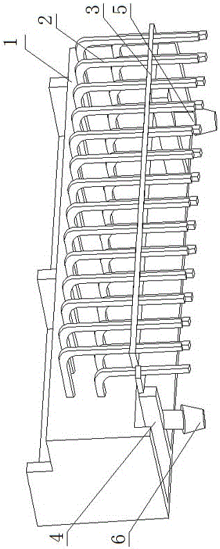
[0027] A design method for a connector that solves the problem of easy upturning, wherein the connector includes a connector body 1 and pins 2, and the lower half of the pin 2 is provided with a positioning plate 3, including the following steps:

[0028] Firstly, the positioning column 4 is set at the bottom of the connector body 1, and the overall displacement of the pin 2 is limited by connecting the positioning column 4 with the positioning plate 3;

[0029] Then, a locking member 5 is provided on the lower side of the positioning column 4, one end of the locking member 5 is connected to the positioning column 4, and the other end is connected to the printed circuit board.

[0030] A connector that solves the problem of easy upturning of universal connectors, including a connector body 1 and pins 2, a positioning plate 3 is provided on the lower half of the pins 2, and two positioning columns 4 are provided at the bottom of the connector body 1 , the positioning column 4 is c

Embodiment 2

[0032] A design method for a connector that solves the problem of easy upturning, wherein the connector includes a connector body 1 and pins 2, and the lower half of the pin 2 is provided with a positioning plate 3, including the following steps:

[0033] Firstly, the positioning column 4 is set at the bottom of the connector body 1, and the overall displacement of the pin 2 is limited by connecting the positioning column 4 with the positioning plate 3;

[0034] Then, a locking member 5 is provided on the lower side of the positioning column 4, one end of the locking member 5 is connected to the positioning column 4, and the other end is connected to the printed circuit board.

[0035] A connector that solves the problem of easy upturning of universal connectors, including a connector body 1 and pins 2, a positioning plate 3 is provided on the lower half of the pins 2, and five positioning columns 4 are provided at the bottom of the connector body 1 , the positioning column 4 is


PUM


Abstract

The invention discloses a connector capable of solving an easy upwarping problem and a design method thereof. The connector comprises a connector body and pins, wherein a positioning plate is arranged at the lower half section of each pin. The design method comprises the following specific steps: firstly setting positioning columns at the bottom of the connector body, and connecting the positioning columns with the positioning plates so as to restrict integral displacement of the pins; and then setting locking pieces on the lower side faces of the positioning columns, wherein one end of each locking piece is connected with the positioning columns, and the other ends of the locking pieces are connected with a printed circuit board. Compared with the prior art, a positioning design is added, the risk of easy upwarping is avoided, the retention force is improved, the using risk is reduced, the reject ratio caused by reduction of the using risk is reduced, the yield is improved, and the cost is reduced; and moreover, the connector is simple in structure, low in cost and high in universality, and can be applied to the design of other connectors of similar structures.

Description


Claims


Application Information

Patent Timeline
Owner LANGCHAO ELECTRONIC INFORMATION IND CO LTD
Why Eureka
Try Eureka