Microelectronic temperature sensor and preparation method thereof

A technology of temperature sensor and microelectronics, applied in thermometers, thermometers using electric/magnetic elements directly sensitive to heat, piezoelectric devices/electrostrictive devices, etc., can solve problems such as high cost, complicated process, and low sensitivity , to achieve the effects of low heat loss, improved sensitivity, and short dynamic response time

Inactive Publication Date: 2016-09-28
HOHAI UNIV CHANGZHOU
View PDF4 Cites 13 Cited by
  • Summary
  • Abstract
  • Description
  • Claims
  • Application Information

AI Technical Summary

Benefits of technology

This patented technical effect of this inventor describes an improved type of thermometer used for measuring temperatures without being affected by electrical currents or other factors like fluctuations caused by changes made during operation. It uses a special kind of material called quartz crystal (C) instead of traditional resistors but still works properly at room temperature. By filling up space between two layers of these materials, the resulting sensor becomes smaller while maintain its ability to measure small amounts accurately over longer periods of time. Additionally, the fabricated sensor does not require any external power supply, making them suitable for integration into electronic devices such as smartphones.

Problems solved by technology

The technical problem addressed in this patented text relates to improving the performance of electronic devices used for measuring temperatures accurately without consuming too much energy during operation. This can help reduce costs associated with maintaining equipment while still being able to measure accurate temperatures even under harsh conditions like extreme cold weather.

Method used


Image

  • Microelectronic temperature sensor and preparation method thereof
  • Microelectronic temperature sensor and preparation method thereof
  • Microelectronic temperature sensor and preparation method thereof

Examples


Embodiment 1

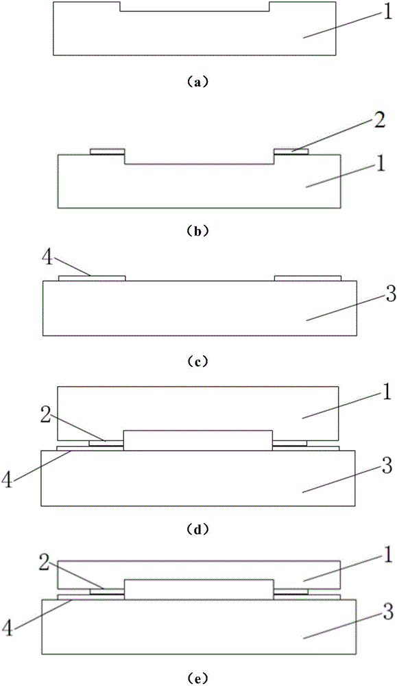
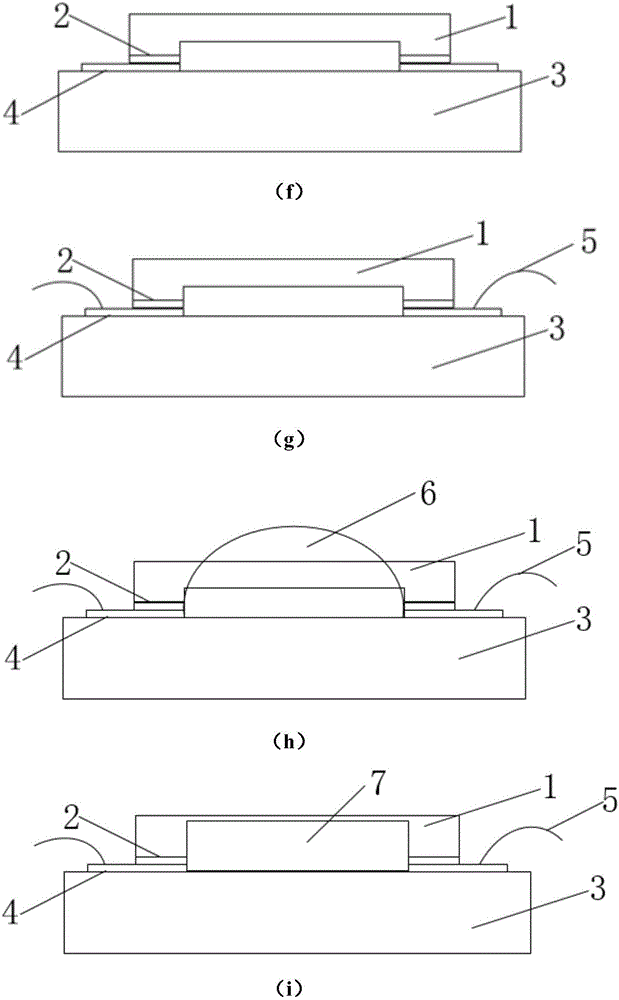
[0019] Such as figure 1 As shown, the microelectronic temperature sensor provided by the invention is prepared through the following steps:

[0020] (a) Etch a shallow trench with a depth of 5 μm on the single crystal silicon substrate 1 by reactive ion etching (RIE);

[0021] (b) Sputter 500Å of Ti on the single crystal silicon substrate 1 as the adhesion material between Au and Si substrate; then sputter 1000Å of Au 2 as the connection material of the low-temperature Au-Au bonding process ;

[0022] (c) On the Pyrex7740 glass substrate 3, 500Å of Ti was firstly sputtered as the adhesion material between Au and the glass substrate, and then 1000Å of Au 4 was sputtered as the connection material of the low-temperature Au-Au bonding process;

[0023] (d) Low-temperature Au-Au bonding is performed on the glass substrate 3 and the single crystal silicon substrate 1, and the bonding process temperature is about 350°C;

[0024] (e) Thinning the monocrystalline silicon substrate 1 t


PUM

PropertyMeasurementUnit
Thicknessaaaaaaaaaa

Abstract

The invention discloses a microelectronic temperature sensor and a preparation method thereof. Specifically, the sensor is a graphene oxide capacitive temperature sensor based on a post-COMS MEMS micro-processing technology. A graphene oxide material is a new type nano-material which has a high dielectric constant, and a dielectric constant value can be changed rapidly along with the change of a temperature. Compared with the temperature sensors such as a common Pt resistor and a PN junction, the microelectronic temperature sensor has the advantages that because a current does not pass through a device, the influence of self-heating effect on a measurement process is avoided when the measurement is carried out, the measurement error is low, the heat loss is low and the dynamic response time is short. Because the dielectric constant of the graphene oxide can be increased rapidly along with the rise of the temperature at the low temperature, a method for detecting a required high-sensitivity temperature sensor at the low temperature is realized. Through combination of the post-COMS MEMS micro-processing technology, the temperature sensor is small in size, low in cost and short in response time.

Description


Claims


Application Information

Patent Timeline
Owner HOHAI UNIV CHANGZHOU
Why Eureka
Try Eureka