Magnesium steam crystallization waste heat utilization device for recycled magnesium smelting

A technology of magnesium smelting and magnesium vapor, which is applied in the field of waste heat utilization devices for magnesium vapor crystallization in recycling magnesium smelting, which can solve the problems of heat waste, large floor space, and high operating costs, and achieve water conservation, construction reduction, and improvement of utilization efficiency Effect

Pending Publication Date: 2017-08-18
ZHENGZHOU UNIV
View PDF6 Cites 0 Cited by
  • Summary
  • Abstract
  • Description
  • Claims
  • Application Information

AI Technical Summary

Benefits of technology

This technology allows for efficient usage of magnetically treated wasted heat from industrial processes by combining two different types of systems with an enclosed pressure tank filled with pure liquid or gas instead of traditional pipes that transport cold water. By doing this, it can improve thermal performance while reducing costly maintenance operations compared to existing techniques like steam injection.

Problems solved by technology

This patented technical problem addressed in this patents relates to reducing energy consumption during production processes for producing metals such as Magnetite or Iron (Fe). Current methods involve removing excessive amounts of steam from these materials before melts are made, but they require expensive equipment that requires significant space usage. Additionally, current techniques have poorly understood how much wasted heat can still occur due to condensations on surfaces where it could affect their performance over time.

Method used


Image

  • Magnesium steam crystallization waste heat utilization device for recycled magnesium smelting
  • Magnesium steam crystallization waste heat utilization device for recycled magnesium smelting

Examples


Embodiment 1

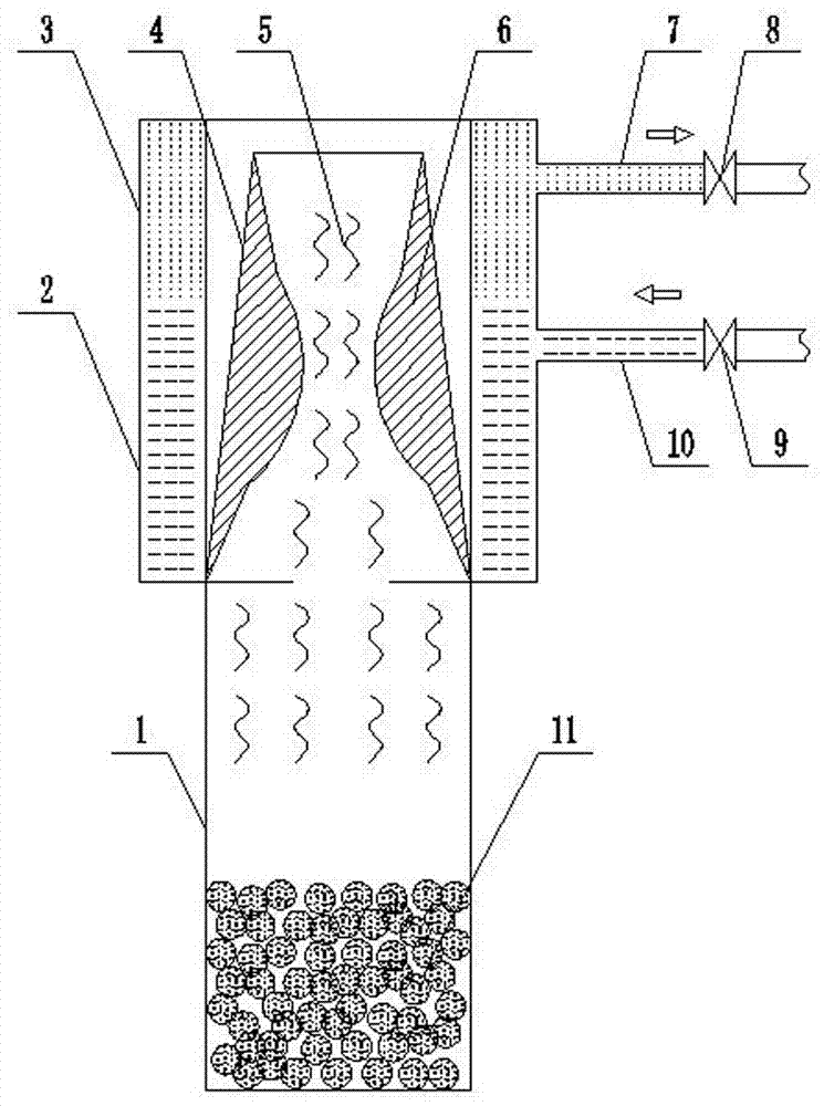
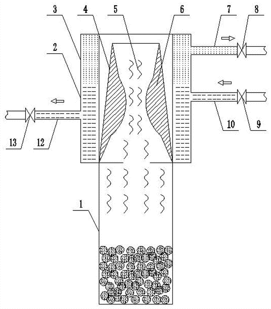
[0011] Embodiment 1: as figure 1 As shown, the present invention includes a vertical tank 1. The upper end of the vertical tank 1 is a magnesium crystallization cylinder 4, and a closed pressure-bearing water jacket is coaxially arranged around the magnesium crystallization cylinder 4 along the circumferential direction. The inner diameter of the airtight pressure-bearing water jacket is Greater than the outer diameter of the magnesium crystallization cylinder 4, the airtight pressurized water jacket consists of a steam section 3 and a water holding section 2 from top to bottom, the steam section 3 and the water holding section 2 are connected, and at the upper end of the steam section 3 A steam outlet pipe 7 is provided, an electromagnetic gas valve 8 is installed on the steam outlet pipe 7, a water inlet pipe 10 is arranged on the upper end of the water holding section 2, and a first electromagnetic water valve 9 is installed on the water inlet pipe 10.

[0012] In the silicon

Embodiment 2

[0014] Embodiment 2: The difference from Embodiment 1 is that a water outlet pipe 12 is provided on the side wall of the water holding section 2, the water outlet pipe 12 is lower than the water inlet pipe 10, and a second electromagnetic water valve is installed on the water outlet pipe 12 13. In this way, dynamically flowing cooling water can be formed in the water storage section 2, thereby further increasing the utilization efficiency of waste heat, which is a cooling water-hot water utilization method.


PUM


Abstract

The invention discloses a magnesium steam crystallization waste heat utilization device for recycled magnesium smelting. The magnesium steam crystallization waste heat utilization device comprises a vertical tank. A magnesium crystallization barrel is arranged on the vertical tank. An airtight pressure-bearing water jacket is coaxially arranged around the magnesium crystallization barrel in the circumferential direction. The inner diameter of the airtight pressure-bearing water jacket is greater than the outer diameter of the magnesium crystallization barrel. The airtight pressure-bearing water jacket is composed of a steam section and a water containing section from top to bottom. The steam section communicates with the water containing section. The upper end of the steam section is provided with a steam outlet pipe. An electromagnetic steam valve is mounted on the steam outlet pipe. The upper end of the water containing section is provided with a water inlet pipe. A first electromagnetic water valve is mounted on the water inlet pipe. Through the arrangement of the airtight pressure-bearing water jacket and coordination of the electromagnetic steam valve, the first electromagnetic water valve and a second electromagnetic water valve, the two cooling effects of cooling water-steam and cooling water-hot water are achieved, effective utilization of magnesium crystallization waste heat is realized, and the utilization efficiency of energy sources is improved. Meanwhile, facilities such as an original cooling tower are omitted. The building cost and operation cost are lowered, and water resources are saved.

Description


Claims


Application Information

Patent Timeline
Owner ZHENGZHOU UNIV
Why Eureka
Try Eureka