Non-condensable gas collecting and spraying energy-saving device of evaporator set

An energy-saving device and evaporator technology, which is applied in the direction of steam condensation, chemical instruments and methods, and the separation of dispersed particles, can solve the problems of large vacuum fluctuations, large energy consumption, and difficult stable control of the evaporator group in the system, so as to improve adhesion , energy saving, high biocompatibility effect

Pending Publication Date: 2018-02-23
GUANGXI HUAYIN ALUMINUM
View PDF19 Cites 0 Cited by
  • Summary
  • Abstract
  • Description
  • Claims
  • Application Information

AI Technical Summary

Benefits of technology

This patented technology describes an improved coating material called Silicon Solar Cells® that helps create better solar cells due to its unique chemical composition. These coatings help prevent moisture ingress during manufacturing processes while still allowing certain gases like oxygen and nitric oxidation to pass into them. By adding these special components onto the substrate beforehand, they become stable when exposed to air without losing their original function. Overall, this new coating provides technical benefits such as enhanced performance, reduced power consumption compared to traditional methods, longer lifespan, increased efficiency, and more efficient use of resources.

Problems solved by technology

This patented technical problem addressed in this patents relates to improving the efficiency and performance of an electrolytical cell used in producing alpha ceramic materials such as Aluminum oxide (AlO). During these operations, there are various sources that consume power but also create unwanted gases like nitrogen dioxides ("NOX"). To address this issue, it suggests adding more efficient heat exchangers with multiple stages instead of just two stage ones. However, even if each stage has its own advantages over others, they still require frequent maintenance because their effectiveness decreased when operated continuously without being able to adjust them accordingly.

Method used


Image

  • Non-condensable gas collecting and spraying energy-saving device of evaporator set
  • Non-condensable gas collecting and spraying energy-saving device of evaporator set

Examples


Embodiment 1

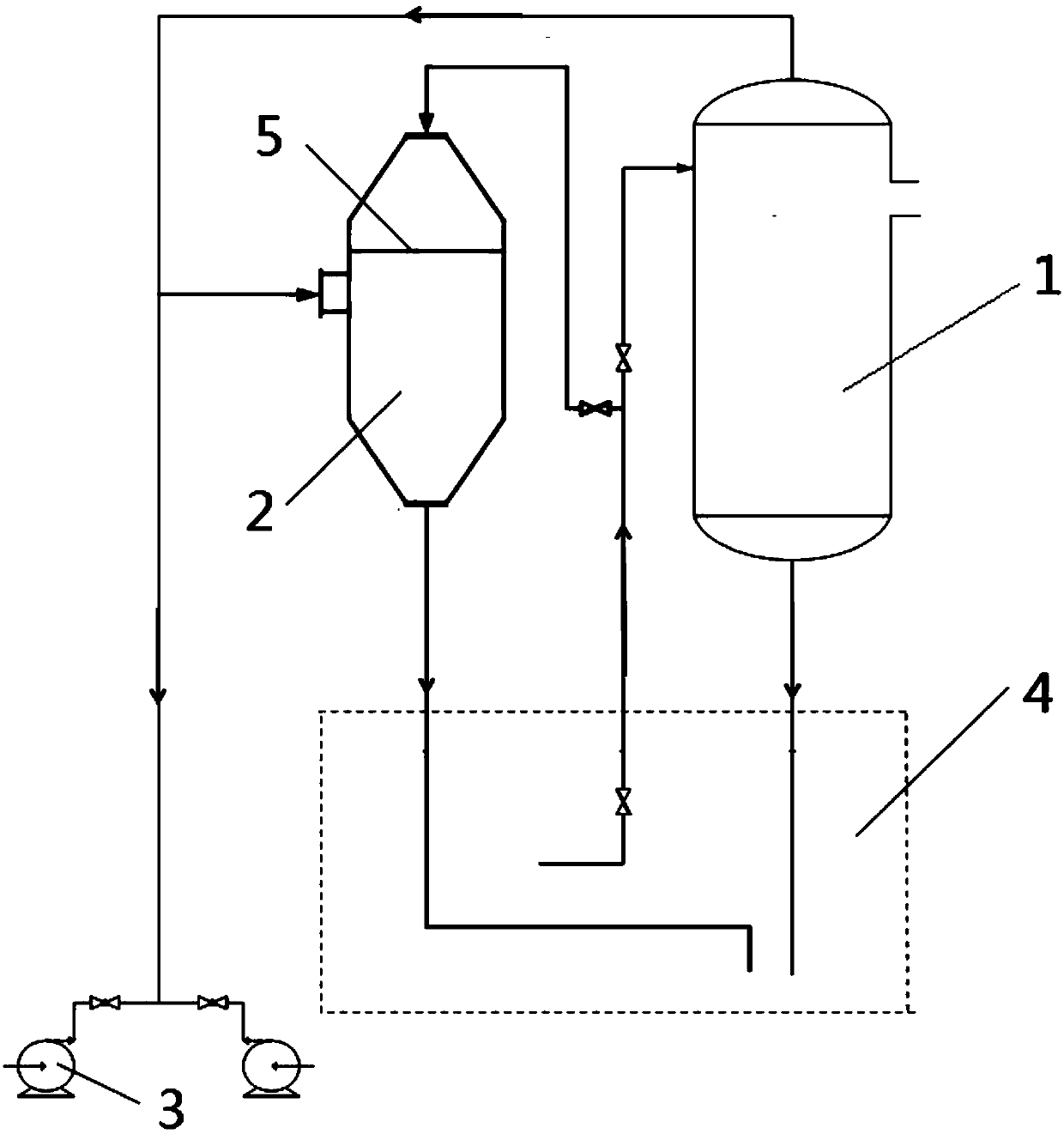
[0036] Such as figure 1 , figure 2 As shown, the non-condensable gas collection and injection energy-saving devices of the evaporator group include:

[0037] The vertically placed cooling tank 2 is used to collect spray condensed non-condensable gas, and its top and bottom are truncated cones, and the middle part is a cylinder; A nozzle is provided; an orifice 5 is also arranged above the nozzle on the side wall of the middle part of the cylinder and below the nozzle on the top of the truncated cone;

[0038] The vertically placed water cooler 1 has nozzles on its top, bottom and upper side walls;

[0039]Vacuum pump 3, which is connected to the nozzle of the side wall of the middle part of the cooling tank 2 cylinder and the nozzle at the top of the water cooler 1 through pipelines;

[0040] The evaporative circulating water system 4 includes a backwater pool, a hot water pool, a hot water pump, a cooling tower, a cold water pool and a cold water pump; The main pipeline of


PUM

PropertyMeasurementUnit
Thicknessaaaaaaaaaa
Diameteraaaaaaaaaa

Abstract

The invention discloses a non-condensable gas collecting and spraying energy-saving device of an evaporator set. The device comprises a water cooler, a vacuum pump, an evaporated water circulating system and a cooling tank, wherein pipe orifices are formed in the top end, the bottom end and the middle side walls of the cooling tank; an orifice plate is arranged above the pipe orifice in the middleside wall of the cooling tank and below the pipe orifice in the top end of the cooling tank; pipe orifices are formed in the top end, the bottom end and the upper side wall of the water cooler; the vacuum pump is connected with the pipe orifice in the middle side wall of a cylinder of the cooling tank and the pipe orifice in the top end of the water cooler through pipelines; pipelines for providing circulatory feeding water of the evaporated water circulating system are respectively connected with the pipe orifices in the side wall of the water cooler and the top end of the cooling tank; andtwo pipelines for receiving circulatory discharged water of the evaporated water circulating system are respectively connected with the pipe orifices in the bottom end of the water cooler and the topend of the cooling tank. According to the device, the cooling tank is additionally arranged, after the evaporator set operates stably, the vacuum effect generated by the cooling tank can replace the vacuum pump, and the vacuum pump stops running, so that the device has an energy-saving effect.

Description


Claims


Application Information

Patent Timeline
Owner GUANGXI HUAYIN ALUMINUM
Why Eureka
Try Eureka