Full-load denitration device with urea fume pyrolysis function

A full-load, urea technology, applied in the direction of gas treatment, membrane technology, dispersed particle separation, etc., can solve the problems of low efficiency, high operating cost, high energy consumption, etc., achieve scientific and reasonable structure, meet the requirements of denitrification, and be widely popularized and applied Effect

Pending Publication Date: 2018-10-02
HUNAN DATANG ENERGY SAVING SCI & TECH CO LTD
View PDF0 Cites 2 Cited by
  • Summary
  • Abstract
  • Description
  • Claims
  • Application Information

AI Technical Summary

Benefits of technology

This patented innovative technology described in this patents allows for effective utilization of waste nitride material (among various types) without requiring expensive materials like punch bars or diesel engines. Additionally, there is no risk associated with traditional methods due to potential issues related to pollutant emissions caused by NOx gases released when burning excessive fuels containing urea instead of coal. Overall, these improvements help reduce environmental hazards and simplify production processes while maintaining economic benefits.

Problems solved by technology

Technological Problem: Current Flameless Boilers Existing Denitrating Technology Using Urease Controlled Thermal Nozzle Reheaters (SCR), which requires expensive equipment due to their limited capacity and require frequent maintenance. There also exist issues related to improving this process without increasing costs associated with new devices like electrical resistance wires used for controlling airflow within the combustion zone.

Method used


Image

  • Full-load denitration device with urea fume pyrolysis function

Examples


Embodiment Construction

[0026] The present invention will be described in detail below in conjunction with the accompanying drawings. As shown in the accompanying drawings:

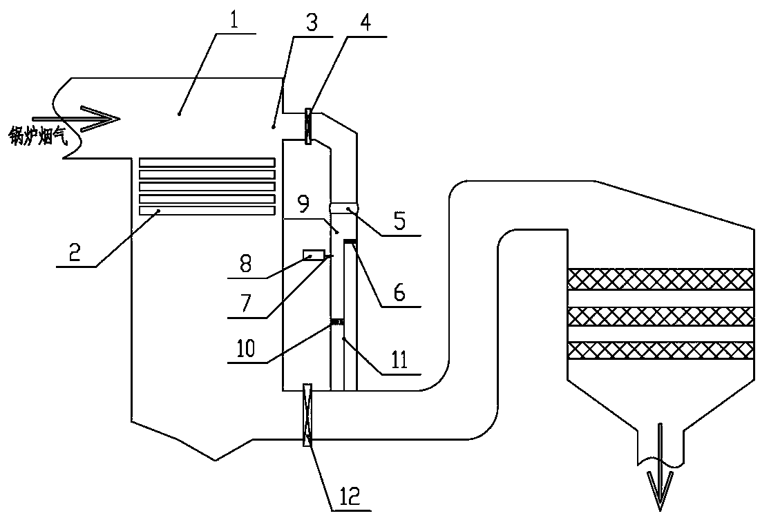
[0027] A full-load denitrification device with urea flue gas pyrolysis function, consisting of 1. tail flue steering chamber, 2. low-temperature superheater, 3. bypass flue inlet, 4. bypass flue adjustment door, 5. expansion Section, 6. Shut-off door, 7. Urea solution spray gun, 8. Urea solution metering and distribution device, 9. Bypass flue, 10. Bypass flue ammonia gas equalization device, 11. Bypass flue partition plate , 12, the main flue regulating door composition.

[0028] The full load denitrification device with urea flue gas pyrolysis function, its bypass flue, bypass flue adjustment door, urea solution metering and distribution device, urea solution spray gun, bypass flue ammonia gas equalization device Fixed connection, the bypass flue is equipped with expansion joints, urea solution metering and distribution devices


PUM


Abstract

The invention discloses a full-load denitration device with a urea fume pyrolysis function and relates to the technical field of boilers. Key techniques of 'urea fume pyrolysis' and 'full-load denitration' are adopted, the device comprises equipment such as a boiler tail flue transferring chamber, a bypass flue, a bypass flue adjusting door, an expansion joint, a closing door, a urea solution metering and allocation device, a urea solution spray gun, an ammonia gas flow equalizing device and a main flue adjusting door, a fume bypass is arranged above a low-temperature overheater in the boilertail flue transferring chamber, an ammonia ejection device and a structure similar to a boiler partition wall are arranged inside the bypass flue, and full-load denitration and urea fume pyrolysis ofa boiler can be carried out. Electric energy and other fuel energy required by urea pyrolysis can be replaced. By adopting the device, equipment such as a urea pyrolysis furnace, a diluted air-power heater or a fuel oil/gas flue heater and an ammonia spraying grid of the prior art can be replaced, and the device is simple and smart in structure, and stable and reliable in effect.

Description


Claims


Application Information

Patent Timeline
Owner HUNAN DATANG ENERGY SAVING SCI & TECH CO LTD
Why Eureka
Try Eureka