Electromagnetic radiation monitor with protection function

A technology of electromagnetic radiation and protection functions, applied in the field of electromagnetic radiation monitors, can solve the problems of low user comfort, the electromagnetic radiation monitor is not convenient for staff to carry, and the electromagnetic radiation monitor does not have a supporting structure, so as to reduce damage The effect of probability

Active Publication Date: 2018-11-13
安徽中知众创知识产权运营有限公司
View PDF8 Cites 1 Cited by
  • Summary
  • Abstract
  • Description
  • Claims
  • Application Information

AI Technical Summary

Problems solved by technology

[0003] The existing electromagnetic radiation monitor does not have a structure that is convenient for the staff to carry. When the staff has a lot of things in their hands, it is not easy to carry, and th

Method used


Image

  • Electromagnetic radiation monitor with protection function
  • Electromagnetic radiation monitor with protection function
  • Electromagnetic radiation monitor with protection function

Examples


specific Embodiment approach

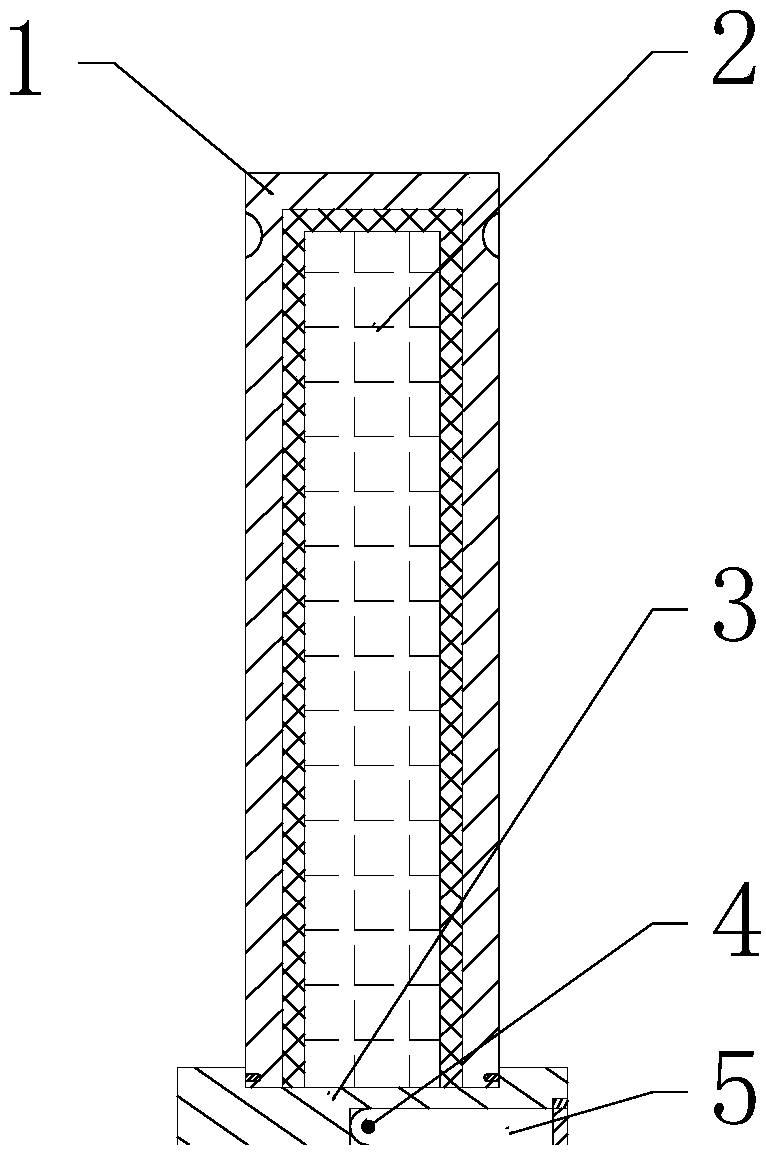
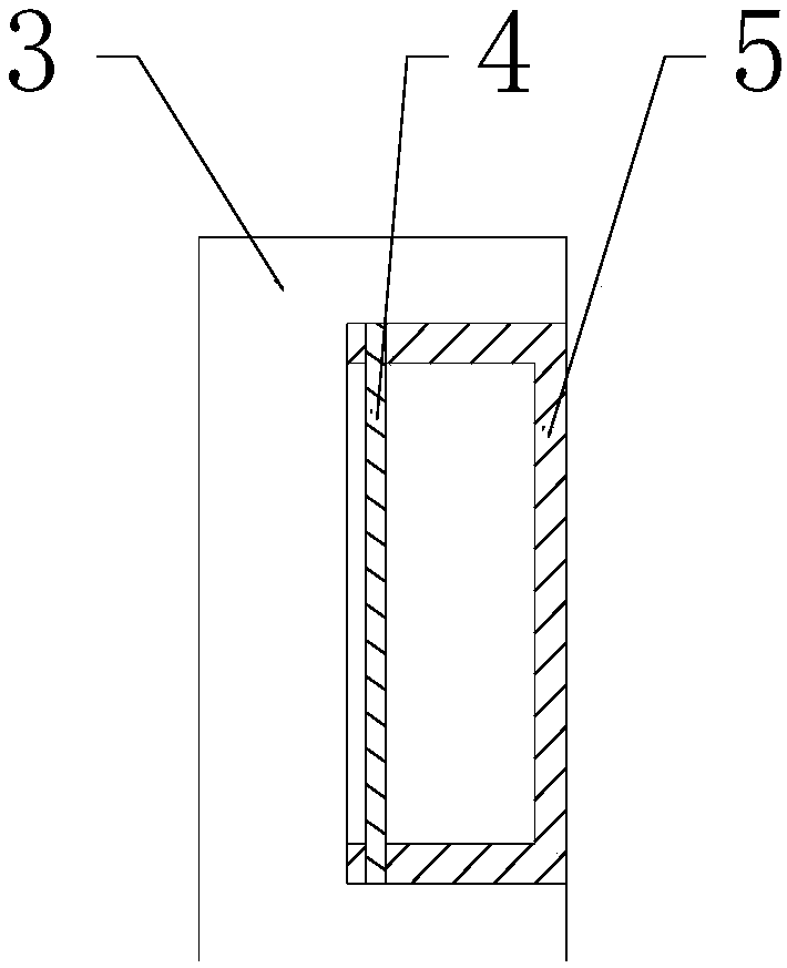
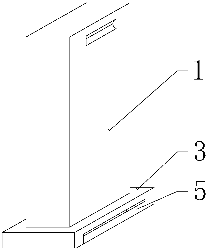
[0024] Specific implementation method: when in use, the staff first turns the present invention 180°, and then rotates the metal U-shaped handle 5 around the rotating shaft 4, so that the metal U-shaped handle 5 is separated from the magnet, and then the metal U-shaped handle 5 is rotated out Set the slot and turn it into place, such as Figure 4 As shown, then the staff utilizes the metal U-shaped handle 5 to carry the present invention to the required position, and then the staff rotates the metal U-shaped handle 5 around the rotating shaft 4 again, so that the metal U-shaped handle 5 is rotated to the inside of the placement groove again, this When the metal U-shaped handle 5 is in contact with the magnet, the magnet generates a magnetic field to adsorb and fix the metal U-shaped handle 5, and then the staff turns the present invention 180° again, and then holds the base 3 with one hand, and uses the protective The groove on the shell 1 moves upward to protect the shell 1, and


PUM


Abstract

The invention provides an electromagnetic radiation monitor with a protection function. The monitor comprises a protection shell, an electromagnetic radiation monitor main body, a pedestal, a rotationshaft and a metal U-shaped handle. The electromagnetic radiation monitor main body is installed in the protection shell. The electromagnetic radiation monitor main body is welded in the pedestal andis extended out of the upper end of the pedestal. The protection shell is installed on the upper end of the pedestal and is extended into the pedestal. A rotating shaft is fixed in the pedestal. The rotating shaft is provided with the metal U-shaped handle. The metal U-shaped handle is installed in the pedestal. The rotating shaft and the metal U-shaped handle are installed on the lower side of the protection shell. The design realizes carrying and supporting functions. The operation is simple, the monitor is portable and a protection function is achieved.

Description


Claims


Application Information

Patent Timeline
Owner 安徽中知众创知识产权运营有限公司
Why Eureka
Try Eureka