Track harvester hydraulic control system and control method

A hydraulic control system and technology for harvesters, which are applied to harvesters, cutters, mechanical equipment, etc., can solve the problems of unreliable steering of rice machines and the inability of multi-way valves to achieve steering priority functions, and achieve simple structure, reliable steering, Action-reliable effects

Pending Publication Date: 2018-12-07
SHENGBANG GRP +3
View PDF0 Cites 1 Cited by
  • Summary
  • Abstract
  • Description
  • Claims
  • Application Information

AI Technical Summary

Problems solved by technology

[0003] In order to solve the problem that the existing multi-way valve in the background technology cannot realize the steering priority function, ma

Method used


Image

  • Track harvester hydraulic control system and control method
  • Track harvester hydraulic control system and control method
  • Track harvester hydraulic control system and control method

Examples


Embodiment 2

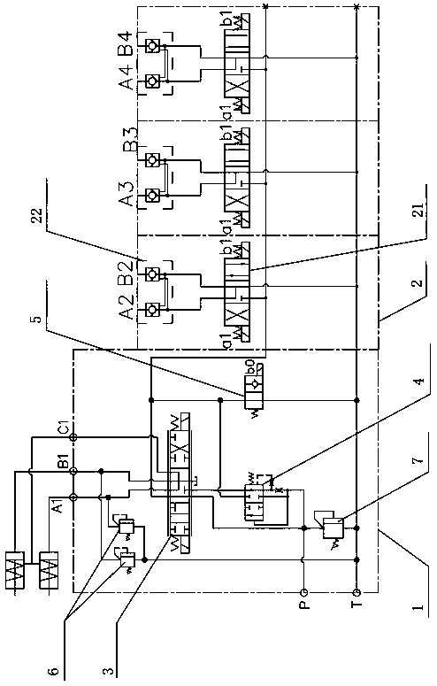
[0027] Embodiment two: see Figure 4 , An electric proportional overflow valve 8 or an electric proportional throttle valve is set between the oil outlet C1 of the steering cylinder and the oil return port T. In the second embodiment, the throttle function of the steering cylinder oil outlet C1 and the control reversing valve 3 in the first embodiment is extracted separately and replaced by an electric proportional overflow valve 8 or an electric proportional throttle valve, so that the steering cylinder can Reliable oil return.

[0028]The right spring chamber 42 of the priority valve is provided with a second throttle hole 46 . The setting of the second throttle hole prevents the priority valve from being impacted during the working process of the system, making the system more stable.

[0029] A hydraulic control method for a crawler harvester, which is characterized in that it includes: ①When the control reversing valve is in the neutral position, the unloading valve is de-


PUM


Abstract

The invention discloses a track harvester hydraulic control system and a control method, and solves the problem of unreliable steering of a paddy machine due to incapability of realizing a steering priority function by a traditional multi-way valve. The track harvester hydraulic control system comprises a main oil inlet, an oil return port, a control valve and a work valve; the control valve comprises a control reversing valve and a priority valve; the control reversing valve is provided with a first position, a second position and a third position; and when the control reversing valve is positioned in the first position and the third position, pressure oil in an oil inlet of the priority valve enters a right side spring cavity of the priority valve through a first throttling hole to cooperate with pressure oil in the oil inlet of the priority valve selected by a left side control cavity of the priority valve for controlling the position of a valve rod of the priority valve. The control method comprises the following steps: when the steering oil cylinder and the work valve are acted, the reversing valve and the priority valve are controlled to realize steering priority actions. Thetrack harvester hydraulic control system has the advantages of simple structure, convenience to assemble, reliable action, long service life and the like.

Description


Claims


Application Information

Patent Timeline
Owner SHENGBANG GRP
Why Eureka
Try Eureka