Purifier for machining and welding of air compressor

A purifier and air compressor technology, applied in chemical instruments and methods, cleaning methods and utensils, removal of smoke and dust, etc., can solve the problems of poor ventilation of the suction arm, affecting the use effect, etc., and achieves advantages of popularization, convenient and practical installation Effect

Inactive Publication Date: 2018-12-11
合肥市科惠特智能科技有限公司
View PDF0 Cites 0 Cited by
  • Summary
  • Abstract
  • Description
  • Claims
  • Application Information

AI Technical Summary

Benefits of technology

This patented technology helps prevent damage or malfunctions during manufacturing processes involving high pressure gas cylinders used by industrial workers such as firefightmen who work near flammable materials like oil fires. It also makes it easier and more efficient to clean up residue that may have accumulated inside these devices after they are installed.

Problems solved by technology

This technical problem addressed by this patented technology relates to improving the efficiency of an air compresser during its operation due to the flexibility provided on certain parts that can be affected when they bend too much causing issues such as insufficiently cooled gases and reduced usability caused by poor ventilations.

Method used


Image

  • Purifier for machining and welding of air compressor
  • Purifier for machining and welding of air compressor

Examples


Embodiment Construction

[0017] The technical solutions in the embodiments of the present invention will be clearly and completely described below in conjunction with the accompanying drawings in the embodiments of the present invention. Obviously, the described embodiments are only a part of the embodiments of the present invention, rather than all the embodiments. Based on the embodiments of the present invention, all other embodiments obtained by those of ordinary skill in the art without creative work shall fall within the protection scope of the present invention.

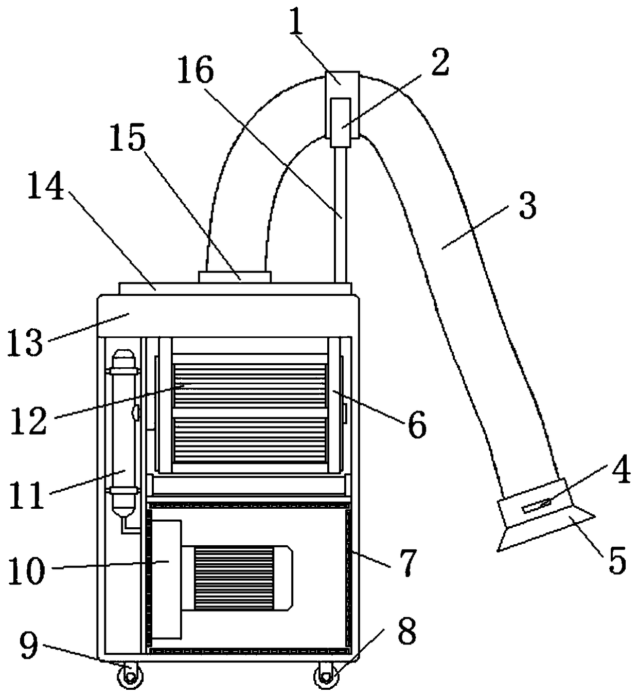
[0018] Such as Figure 1-2 As shown, the present invention provides a technical solution: a purifier for air compressor processing and welding, comprising a purifying box 13, a purifying filter cartridge 12, a fan 10, and an air bag 11. The purifying filter cartridge 12 is fixed on the rack 6 On the inner wall of the upper end of the purification box 13, the fan 10 is installed at the lower end of the interior of the purification box 13, an


PUM


Abstract

The invention discloses a purifier for machining and welding of an air compressor. The purifier for machining and welding of the air compressor comprises a purifying box, a purifying filter cartridge,a fan and an air manifold, wherein the purifying filter cartridge is fixed on the inner wall of the upper end of the purifying box through a hanger; the fan is mounted at the lower end of the insideof the purifying box; the air manifold is arranged on one side of the fan and one side of the purifying filter cartridge; the top surface of the purifying box is rotatably connected with an air suction arm through a connecting ring; a dust collecting cover is fixedly arranged at the lower end of the air suction arm; a fixing plate is further fixedly arranged on the top surface of the purifying box; a circle of annular sliding track is further arranged at the outer edge of the top surface of the fixing plate; the annular sliding track is slidably connected with a slider; a stand column is fixedly arranged on the slider; a U-shaped fixing seat is fixedly arranged at the upper end of the stand column; the outer side of the air suction arm is further fixedly connected with a fixing ring in a sleeving manner; and the fixing ring can be in clamped connection to the U-shaped fixing seat. The problems that if an air suction arm of an existing welding purifier is bent extensively, unsmooth ventilation is easily caused, and the using effect is affected are solved.

Description


Claims


Application Information

Patent Timeline
Owner 合肥市科惠特智能科技有限公司
Why Eureka
Try Eureka