Waste liquid and waste gas treatment system
A technology for waste gas treatment and waste liquid, which is applied in the direction of gaseous effluent wastewater treatment, biological water/sewage treatment, water/sludge/sewage treatment, etc. It can solve problems such as high process requirements, environmental pollution, and inability to apply in large quantities
- Summary
- Abstract
- Description
- Claims
- Application Information
AI Technical Summary
Problems solved by technology
Method used
Image

Examples
Embodiment 1
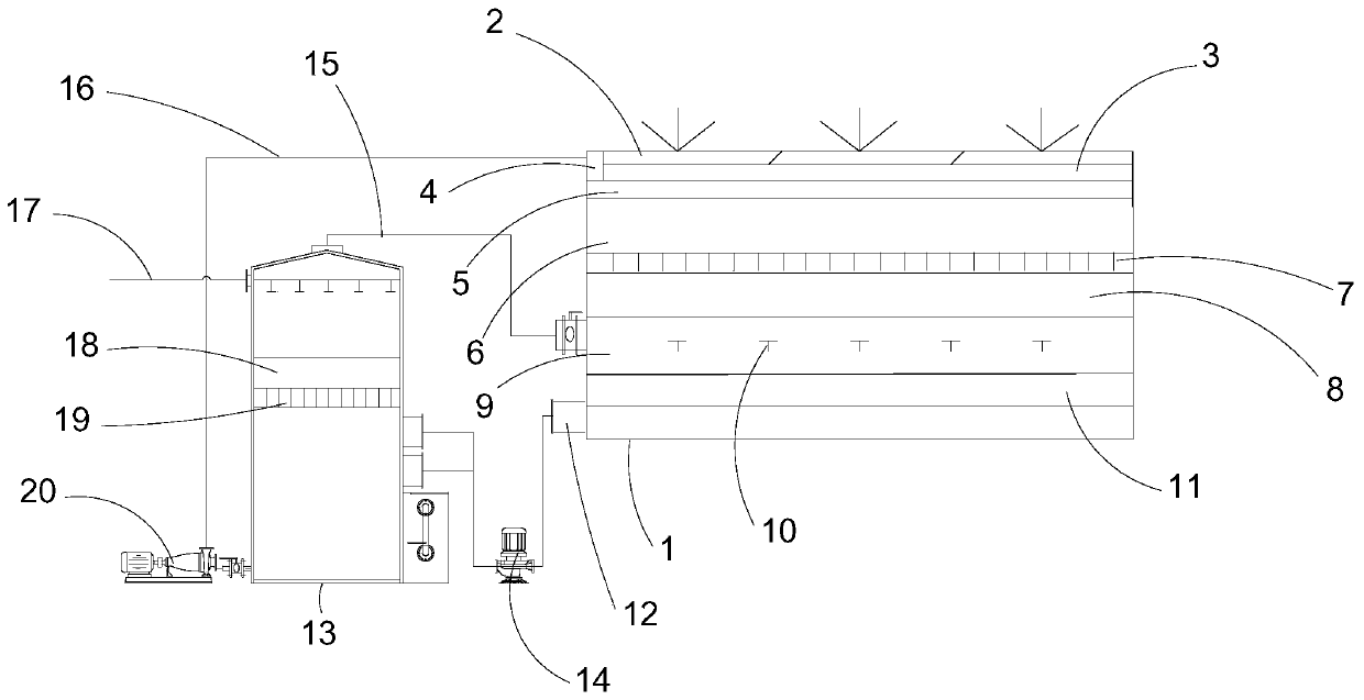
[0039] Combined with the actual project, the design of the cold process side suction hood in the external hood is adopted to facilitate the installation of pipes and fans. The exhaust air volume of the side suction hood is determined by the control speed method, and its start-up is based on the pressure of the production workshop. Sensors and odor detectors are connected to the PLC control system for automatic control. The control parameters are as follows:
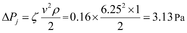
[0040] The pressure loss and velocity distribution of the exhaust hood depend on the expansion angle θ of the exhaust hood. When the θ angle is 30°~60°, the pressure loss reaches the minimum. Considering the tuyere velocity of the hood, the specific structure, and the pressure loss comprehensively, θ is taken as 60°. At this time, ζ 0 =0.16
[0041]
[0042] In the formula:
[0043] ζ——local resistance coefficient;
[0044] V——wind speed of the hood, m / s;
[0045] ρ——gas density, kg / m 3 .
Embodiment 2
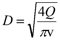
[0047] The diameter of the spray tower is determined by the flue gas volume in the tower, and the gas flow rate in the spray tower is guaranteed to be less than or equal to 4m / s. Since the flue gas volume is a definite value in the design, the flow rate of the flue gas in the spray tower depends on the area of the spray tower. When the flow rate increases, the diameter of the tower decreases and the engineering cost decreases, which is conducive to the heat transfer and mass transfer. However, if the residence time of the gas in the tower is too short, the absorption efficiency will decrease. When the flow rate decreases, the diameter of the absorption tower increases, and the low flow rate is not conducive to the effect of heat and mass transfer. The phenomenon of "escape" of the dripping liquid in the demister is more obvious, but the gas stays in the tower for a long time and the reaction is relatively sufficient. The case of the present invention selects the intake air v...
Embodiment 3
[0055] The ecological filter bed micro-irrigation system is composed of water source, head hub, water transmission and distribution pipe network and sprinkler, as well as flow pressure control components and measuring instruments, and is connected with the PLC automatic control system.
[0056] a. Pipelines are divided into three levels: main pipes, branch pipes and capillary pipes. The main pipes are set according to the elevation, the main branch pipes are set according to the short side parallel to the short side of the rectangular container, and the capillary pipes are arranged according to the long side parallel to the container. For setting, the length of each branch pipe is 6.0m, and the interval distance is 1.0m.
[0057] b. Set a capillary tube for any row of plants, install a sprinkler for a certain plant area, set the outlet of the small tube in the plant ring ditch, use a special puncher to punch a Ф4 hole in the capillary tube, so that the current stabilizer and th...
PUM
| Property | Measurement | Unit |
|---|---|---|
| Outer diameter | aaaaa | aaaaa |
| Wall thickness | aaaaa | aaaaa |
| Nominal pressure | aaaaa | aaaaa |
Abstract
Description
Claims
Application Information
 - R&D Engineer
- R&D Manager
- IP Professional
- Industry Leading Data Capabilities
- Powerful AI technology
- Patent DNA Extraction
Browse by: Latest US Patents, China's latest patents, Technical Efficacy Thesaurus, Application Domain, Technology Topic.
© 2024 PatSnap. All rights reserved.Legal|Privacy policy|Modern Slavery Act Transparency Statement|Sitemap