Layer change structure
A layer structure and base layer technology, applied in the display field, can solve the problems of easy corrosion and poor film quality, and achieve the effect of avoiding the location of steep slopes, reducing the risk of corrosion, and avoiding too steep film formation.
- Summary
- Abstract
- Description
- Claims
- Application Information
AI Technical Summary
Problems solved by technology
Method used
Image

Examples
Embodiment 1
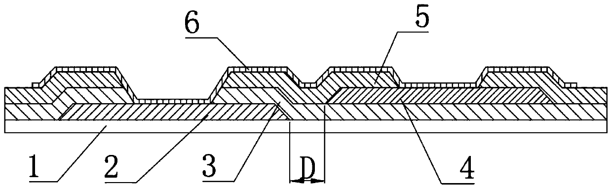
[0021] Such as figure 1 As shown, it shows a layer-changing structure provided by the present invention. This layer-changing structure is applied to a display panel, including a base layer 1, a first metal layer 2 disposed on the base layer 1, a first insulating layer 3 disposed on the first metal layer 2 and the base layer 1 , the second metal layer 4 disposed on the first insulating layer 3 , the second insulating layer 5 disposed on the second metal layer 4 and the first insulating layer 3 and the second On the insulating layer 5 and extending from the first metal layer 2 to the ITO layer 6 on the second metal layer 4; the second metal layer 4 is not connected with the first metal layer 2 A gap D is formed between the overlapping and the second metal layer 4 so that the ITO layer 6 forms a flat segment at a position corresponding to the gap D.
[0022] Specifically, in this embodiment, via holes are provided on the first insulating layer 3 and the second insulating layer 5 a
Embodiment 2
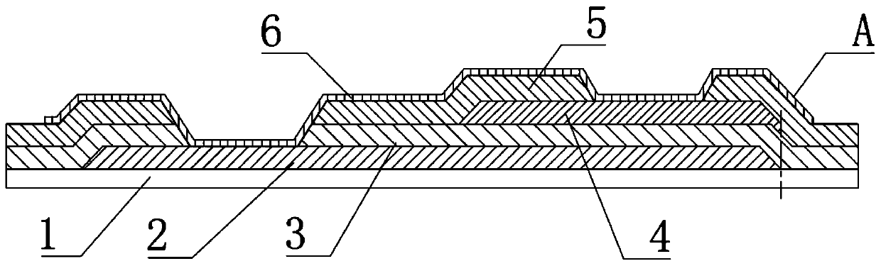
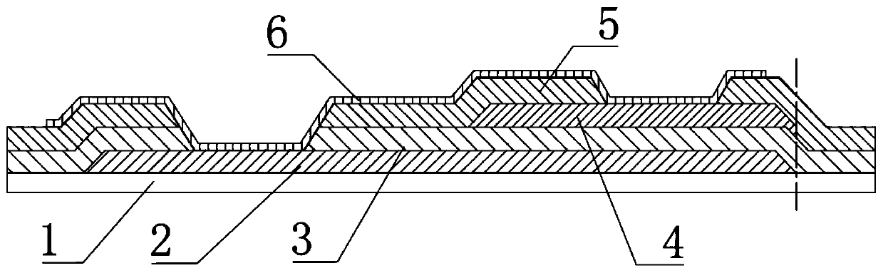
[0026] Such as figure 2 As shown, it shows a layer-changing structure provided by this embodiment. The layer-change structure includes a base layer 1, a first metal layer 2 disposed on the base layer 1, a first insulating layer 3 disposed on the first metal layer 2 and the base layer 1, and a first layer of insulating layer 3 disposed on the first metal layer 2 and the base layer 1. The second metal layer 4 on the first insulating layer 3, the second insulating layer 5 on the second metal layer 4 and the first insulating layer 3 and the second insulating layer 5, and Extending from the first metal layer 2 to the ITO layer 6 on the second metal layer 4 ; the first metal layer 2 extends below the second metal layer 4 .
[0027] Similar to the previous embodiment, the first insulating layer 3 and the second insulating layer 5 are provided with via holes at positions corresponding to the first metal layer 2, and the second insulating layer 5 A via hole is provided at a position co
PUM
 Abstract
Description
Claims
Application Information
 - R&D Engineer
- R&D Manager
- IP Professional
- Industry Leading Data Capabilities
- Powerful AI technology
- Patent DNA Extraction
Browse by: Latest US Patents, China's latest patents, Technical Efficacy Thesaurus, Application Domain, Technology Topic.
© 2024 PatSnap. All rights reserved.Legal|Privacy policy|Modern Slavery Act Transparency Statement|Sitemap