Automatic mechanical equipment lifting device

A lifting device and mechanical equipment technology, applied in transportation and packaging, load hanging components, non-rotational vibration suppression, etc., can solve the problems of no anti-slip mechanism on the load-bearing plate, large ground vibration, etc., to improve safety, Effect of reducing influence of vibration

Active Publication Date: 2019-06-14
平庆义
View PDF11 Cites 1 Cited by
  • Summary
  • Abstract
  • Description
  • Claims
  • Application Information

AI Technical Summary

Problems solved by technology

[0004] The purpose of the present invention is to solve the shortcomings of the prior art that the load-bearing plate is not provided

Method used


Image

  • Automatic mechanical equipment lifting device
  • Automatic mechanical equipment lifting device
  • Automatic mechanical equipment lifting device

Examples


Embodiment Construction

[0026] The following will clearly and completely describe the technical solutions in the embodiments of the present invention with reference to the accompanying drawings in the embodiments of the present invention. Obviously, the described embodiments are only some, not all, embodiments of the present invention.

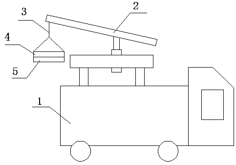
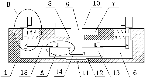
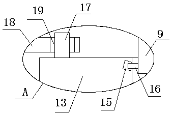
[0027] refer to Figure 1-6 , an automatic mechanical equipment lifting device, comprising a crane 1, the top side of the crane 1 is provided with a boom 2, the top of the boom 2 passes through a traction rope 3, a load-bearing plate 4 is movably installed, and the bottom side of the load-bearing plate 4 is fixedly installed with a The buffer plate 5 and the load-bearing plate 4 are provided with an installation cavity 6, the top side of the load-bearing plate 4 is provided with a groove 7, and the inner wall of the bottom side of the groove 7 is provided with a pressure hole 8, and the pressure hole 8 is connected with the installation cavity 6 Through, the lower press


PUM


Abstract

The invention belongs to the technical field of lifting devices, and particularly relates to an automatic mechanical equipment lifting device. The scheme of the automatic mechanical equipment liftingdevice aims at the defects that an existing bearing plate is not provided with any anti-slip mechanism and is large in grounding vibration. According to the scheme, the automatic mechanical equipmentlifting device comprises a crane; a lifting rod is arranged on the top side of the crane; a bearing plate is movably arranged at the top end of the lifting rod through a traction rope; a buffer plateis fixedly arranged on the bottom side of the bearing plate; a mounting cavity is formed in the bearing plate; and a groove is formed in the top side of the bearing plate. Hoisting operation is carried out on mechanical equipment to be hoisted through the hoisting rod and traction rope on the crane. After the mechanical equipment is placed on the bearing plate, two baffles get close to each otherto clamp the mechanical equipment to be hoisted, so that the mechanical equipment is prevented from slipping off the bearing plate in the hoisting and transferring process. When the bearing plate falls off, vibration which is generated when the bearing plate falls onto the ground is substantially counteracted through the buffer plate, the influence of vibration on the mechanical equipment is obviously reduced, and the safety of hoisting and transferring the mechanical equipment is improved.

Description


Claims


Application Information

Patent Timeline
Owner 平庆义
Why Eureka
Try Eureka