Heating U-shaped tower tube multi-phase-flow boosting turbine motor high-efficiency circulation power generation device

A cycle power generation and multi-phase flow technology, which is applied to steam engine devices, machines/engines, mechanical equipment, etc., can solve the problem that the energy conversion rate cannot reach the optimal state, the ratio of steam flow rate to speed is not uniform, and the utilization rate of steam energy is not uniform, etc. problem, to achieve the effect of high drive energy mechanical shaft power conversion efficiency, large drive energy, and high recycling rate

Pending Publication Date: 2019-06-18
李福军
View PDF0 Cites 0 Cited by
  • Summary
  • Abstract
  • Description
  • Claims
  • Application Information

AI Technical Summary

Problems solved by technology

Existing boilers have a small heating and heat transfer area, and are generally in a laminar flow state, with low heat transfer efficiency; they do not make full use of the kinetic energy of steam, let alone the kinetic energy of water; they do not make full use of the phase change energy of vaporized gas, and the After absorbing heat, energy is obtained to break free from the shackles of water molecules, and the phase changes into a gas phase, and a large amount of gas phase that has done work produces a reverse phase change in the cooling tower, and the phase change in the gas phase can be absorbed by the cooling liquid to change the gas phase into a liquid Phase, phase change energy is wasted; because the temperature and pressure change during the steam work process, so its volume flow rate also changes, but the speed of the turbine blades is generally the same, which leads to the difference between the steam flow rate and the speed of each blade. The ratio is not uniform, resulting in the utilization rate of steam energy is not uniform, and the energy conversion rate cannot reach the optimal state

Method used


Image

  • Heating U-shaped tower tube multi-phase-flow boosting turbine motor high-efficiency circulation power generation device
  • Heating U-shaped tower tube multi-phase-flow boosting turbine motor high-efficiency circulation power generation device

Examples


Embodiment Construction

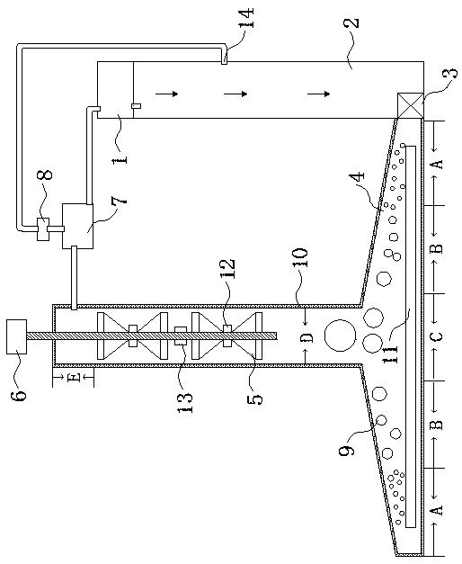
[0014] Such as figure 1 As shown, the heating U-shaped tower tube multiphase flow booster turbine high-efficiency cycle power generation device of the present invention is composed of a cooler 1, a cooling tower tube 2, a liquid supply booster 3, a heating tower tube 4, and a multi-stage multi-stage turbine unit 5. A generator 6, a gas-liquid separator 7 and an exhaust converter 8 are formed. The cooler 1 is connected to the cooling tower pipe 2, and low-temperature water is injected into the cooling tower pipe 2. The cooling tower pipe 2 is provided with a gas inlet 14, Inject dissolved gas into the cooling tower tube 2 through the gas inlet 14 to dissolve and form saturated dissolved gas water. The heating tower tube 4 is composed of a chassis 9 and a vertical tower tube 10. The heating chassis 9 is a flat plate to increase the heat exchange area and heat exchange efficiency. , in order to make full use of low-energy density and large-capacity clean energy (solar energy, geo...


PUM


Abstract

The invention discloses a heating U-shaped tower tube multi-phase-flow boosting turbine motor high-efficiency circulation power generation device and belongs to the field of vary-volume engine devicesof hot gas or combustion products. The device is composed of a cooler, a cold water tower tube, a liquid supplr booster, a heating tower tube, a multi-section multi-stage turbine set, a power generator, a gas-liquid separator and an exhausting converter. The heating tower tube is composed of a chassis and a vertical tower tube; the bottom of the cold water tower tube is connected with the chassisof the heating tower tube, and the liquid supply booster is disposed in the connection position of the bottom of the cold water tower tube and the chassis of the heating tower tube; a heating coil isdisposed in the chassis; the multi-section multi-stage turbine set is disposed in the vertical tower tube; an output shaft of the multi-section multi-stage turbine set is connected with the power generator; a top opening of the vertical tower tube is connected to the gas-liquid separator; an upper outlet of the gas-liquid separator is connected with the exhausting converter; and an outlet of theexhausting converter is connected to the cold water tower tube. According to the device, many types of driving energy exist, all types of driving energy are high, the driving energy mechanical shaft work conversion efficiency is high, ineffective energy consumption is small, and the recovery rate of liquid residues, various gas residues and various energy residues is high.

Description

technical field [0001] The invention relates to the field of variable capacity engine devices for hot gas or combustion products, in particular to a high-efficiency cycle power generation device for heating U-shaped tower tube multiphase flow booster turbines. Background technique [0002] At present, when the turbine generates electricity, the water in the heating boiler is turned into water vapor, and the turbine drives the generator to generate electricity. Existing boilers have a small heating and heat transfer area, and are generally in a laminar flow state, with low heat transfer efficiency; they do not make full use of the kinetic energy of steam, let alone the kinetic energy of water; they do not make full use of the phase change energy of vaporized gas, and the After absorbing heat, energy is obtained to break free from the shackles of water molecules, and the phase changes into a gas phase, and a large amount of gas phase that has done work produces a reverse phase...

Claims


Application Information

Patent Timeline
IPC IPC(8): F01K25/04F01D15/10
Inventor 李福军
Owner 李福军
Why Eureka
Try Eureka