Electric air compressor with motor rotor cooling system

An electric air compressor and rotor cooling technology, which is applied in the direction of machines/engines, electric components, cooling/ventilation devices, etc., can solve the problems of increasing manufacturing and use costs, cooling, etc., to reduce manufacturing and use costs, and save assembly space Effect

Inactive Publication Date: 2019-08-20
DALIAN MARITIME UNIVERSITY
View PDF15 Cites 2 Cited by
  • Summary
  • Abstract
  • Description
  • Claims
  • Application Information

AI Technical Summary

Benefits of technology

The technical feature described by this patented technology relates to an electrical pneumatic compression machine that uses heat from both the motors' stator coils (their internal parts) for better performance at higher speeds when used alone or together. It eliminated any extra external devices like water circulation systems needed due to lack thereof. By doing away with these things, there was no longer too much weight being placed onto them during operation. Overall, this design made up more efficient and effective machines possible because they didn’t require expensive materials themselves.

Problems solved by technology

This technical problem addressed in this patented text relates to improving the efficiency or performance of electrical compressed air systems by reducing their temperature during startups while still maintaining stability over time.

Method used


Image

  • Electric air compressor with motor rotor cooling system
  • Electric air compressor with motor rotor cooling system
  • Electric air compressor with motor rotor cooling system

Examples


Embodiment Construction

[0024] In order to make the purpose, technical solutions and advantages of the embodiments of the present invention clearer, the technical solutions in the embodiments of the present invention will be clearly and completely described below in conjunction with the drawings in the embodiments of the present invention. Obviously, the described embodiments It is a part of embodiments of the present invention, but not all embodiments. Based on the embodiments of the present invention, all other embodiments obtained by persons of ordinary skill in the art without creative efforts fall within the protection scope of the present invention.

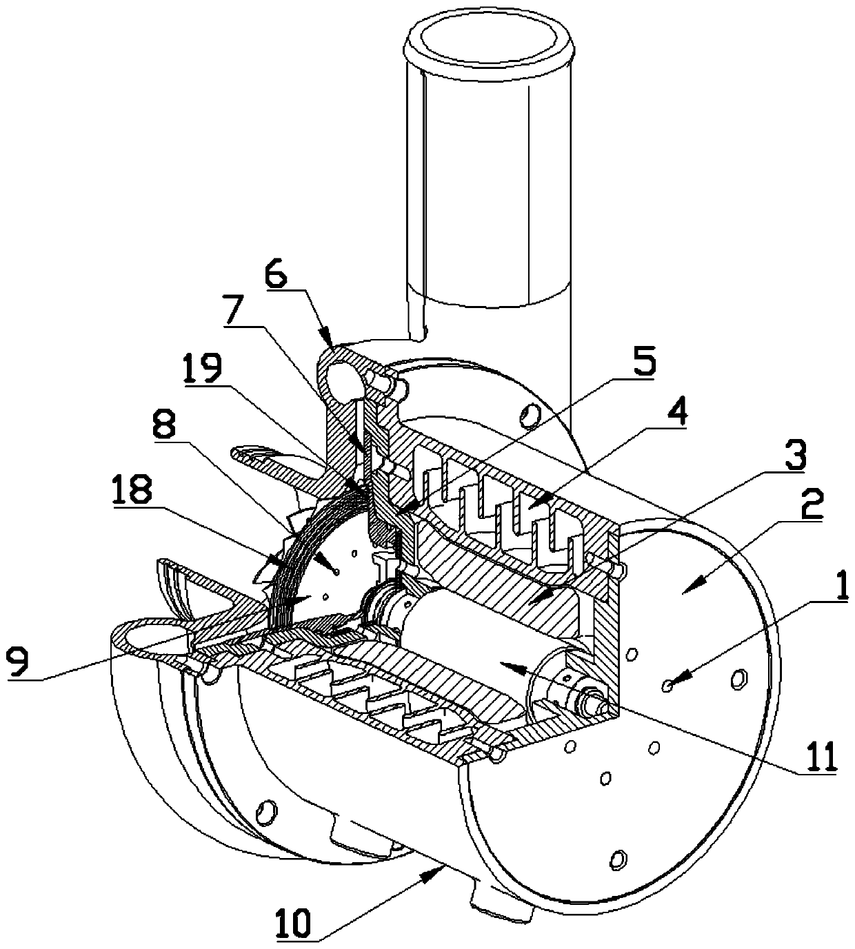
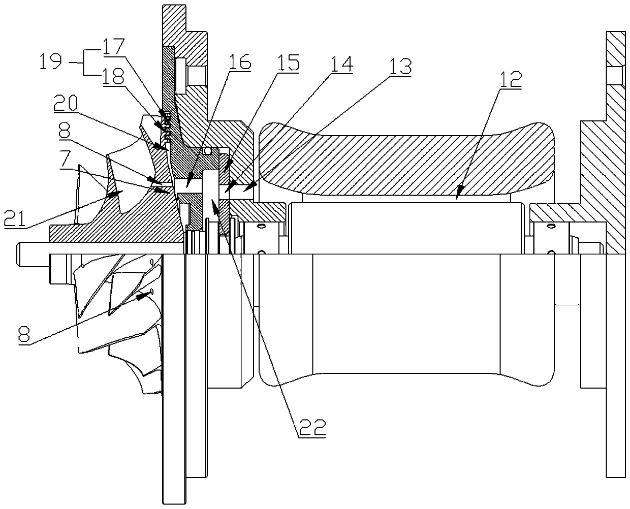
[0025] Such as Figure 1-6 As shown, an electric air compressor with a motor rotor cooling system disclosed in the present invention includes an impeller 21, an air seal 19, an impeller back plate cover plate 7, a thrust bearing 15, and a bearing cover 5 arranged in sequence along the axial direction. and motor 10;

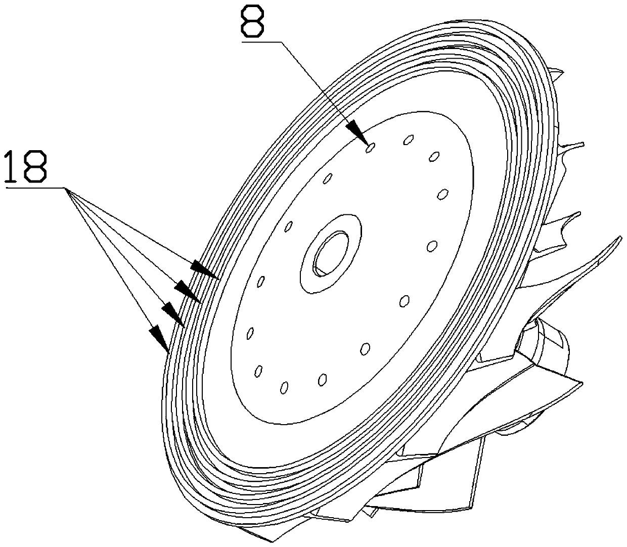
[0026] The impeller 21 includes


PUM

PropertyMeasurementUnit
Heightaaaaaaaaaa
Thicknessaaaaaaaaaa

Abstract

The invention discloses an electric air compressor with a motor rotor cooling system. The electric air compressor comprises an impeller, an impeller back plate cover plate, a thrust bearing, a bearingcover and a motor which are sequentially arranged in the axial direction, an impeller air inlet hole is formed in the impeller, a back plate cover plate cooling hole is formed in the impeller back plate cover plate, a thrust bearing cooling hole and a bearing cover cooling hole are formed in the thrust bearing and the bearing cover respectively, air passes through holes in the impeller, the impeller back plate cover plate, the bearing and the bearing cover to reach between the motor rotor and a motor stator, and finally is discharged from a motor rear end cover. The electric air compressor effectively cools the motor rotor and does not need to be provided with an additional cooling device, so that the manufacturing cost and the use cost are reduced, and the assembly space is saved.

Description


Claims


Application Information

Patent Timeline
Owner DALIAN MARITIME UNIVERSITY
Why Eureka
Try Eureka