Flue gas waste heat exchange device with dirt accumulation prevention function

A flue gas waste heat and exchange equipment technology, which is applied in the field of flue gas waste heat recovery, can solve problems such as unfavorable maintenance and replacement, dirt cleaning, bulky heat exchanger, and complicated spiral structure, so as to reduce maintenance and use costs and improve economic benefits , Simple and compact structure

Active Publication Date: 2019-12-03
HARBIN ENG UNIV
View PDF12 Cites 0 Cited by
  • Summary
  • Abstract
  • Description
  • Claims
  • Application Information

AI Technical Summary

Benefits of technology

This new design allows the machine to keep itself free from getting dirty quickly without losing its effectiveness or performance due to deposits that may be left behind overtime. It achieves this through continuous circulation between two parts called an exchanger tube where fluids flow while they pass through them. By constantly shaking off any debris attached to these surfaces, the system keeps working well even after multiple uses. Additionally, the apparatus doesn't have extra components like filters needed but only requires regular cleanings. Overall, this technology improves energy utilization and extends lifespan of the machines.

Problems solved by technology

This patented technical describes different ways to recover or reuse wasted heat from combustion processes without causing environmental concerns like air quality issues (CO2). However, current methods have limitations due to deposits formed over time when used alone. There exists a new method called Self-Cleaning Fluoride Gas Plasma Exhaverbercy System (SCFES) described earlier in the literature. These systems aim to remove unwanted debris while keeping them inside the system's own unit. They use special materials made up mostly of stainless steel instead of traditional metals, making their construction simpler compared to other options currently available. Additionally, they provide better control capabilities at both coolant temperature and pressure levels. Overall, SCFEMS provides a simplified and effective means to recycle excessive waste heat generated by industry facilities.

Method used


Image

  • Flue gas waste heat exchange device with dirt accumulation prevention function
  • Flue gas waste heat exchange device with dirt accumulation prevention function
  • Flue gas waste heat exchange device with dirt accumulation prevention function

Examples


Embodiment Construction

[0014] The present invention will be further described below in conjunction with the accompanying drawings.

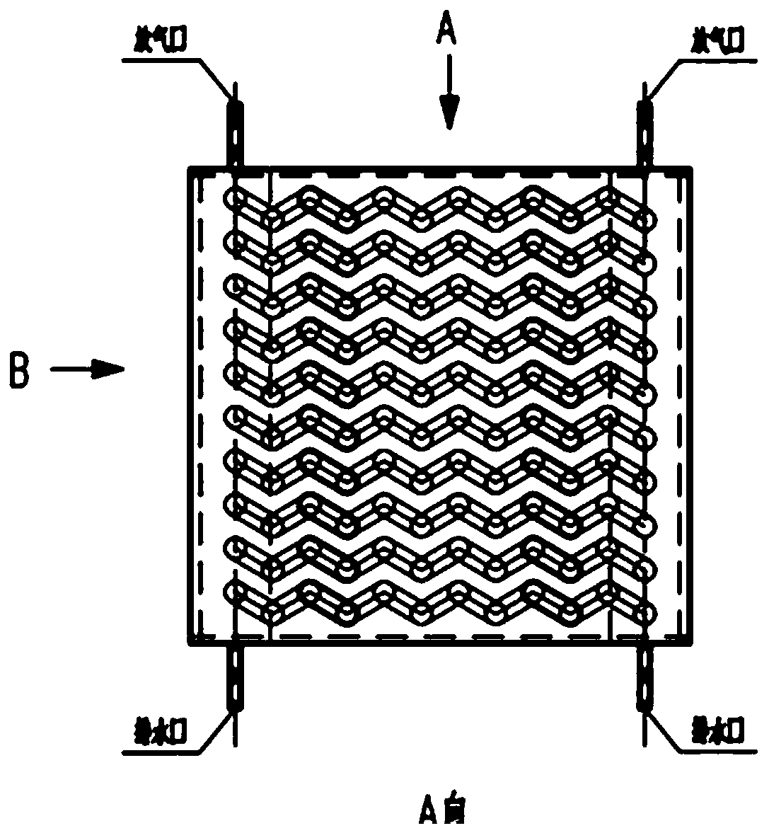
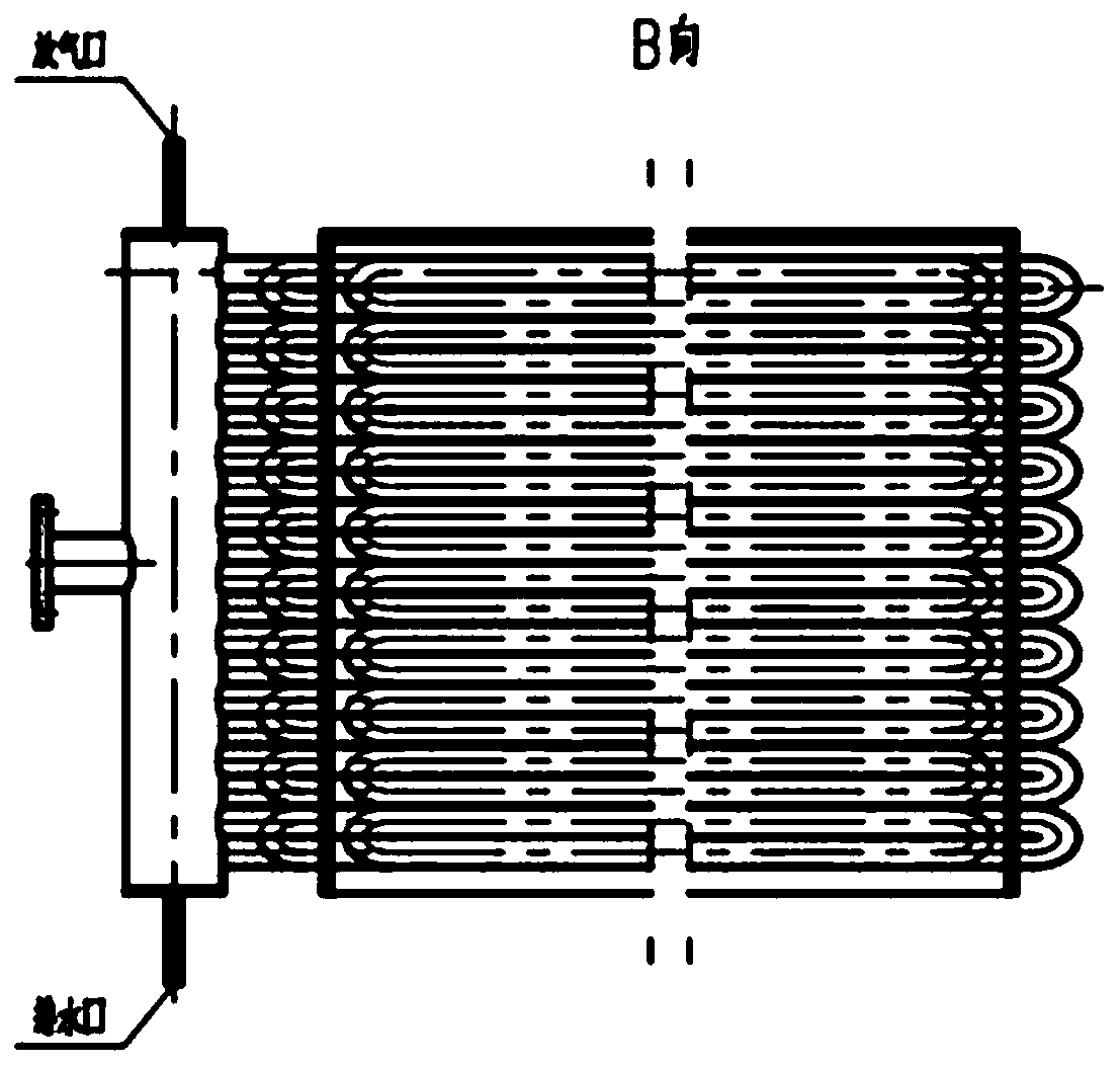
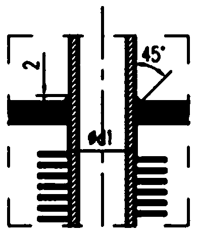
[0015] Figure 4 Middle: 1-box, 2-inlet header, 3-outlet header, 4-U-shaped spiral finned tube, 5-flue gas inlet, 6-flue gas outlet.

[0016] The purpose of the present invention is to provide a new waste heat exchange device with the function of self-maintaining cleanliness and avoiding the accumulation of dirt, aiming at the problem of fouling of common industrial flue gas waste heat recovery devices.

[0017] A flue gas waste heat exchange device with the function of preventing dirt accumulation, including a box body, a U-shaped spiral finned tube, an inlet header, an outlet header, a flue gas outlet, and a flue gas inlet. The U-shaped spiral finned tube is connected to In the inlet header and the outlet header, the inlet header is equipped with an air vent and a drain, and the outlet header is equipped with an air vent and a drain, and the inside of the box includes


PUM


Abstract

The invention belongs to the technical field of flue gas waste heat recovery, in particular to a flue gas waste heat exchange device with a dirt accumulation prevention function. The device consists of a box body, a U-shaped spiral finned tube, an inlet header, an outlet header, a flue gas outlet and a flue gas inlet, one end of the U-shaped spiral finned tube is connected with the inlet header, and the other end is connected with the outlet header; a water injection port and a gas exhaust port are formed on the inlet header, a water drainage port and a gas exhaust port are formed on the outlet header, and a smoke inlet is formed at the side, close to the inlet header, of the box body; the smoke outlet is formed at the side, close to the outlet header, of the box body, and the U-shaped spiral finned tubes are installed in the box body layer by layer. The device can continuously keep the self-cleaning capacity from the beginning of operation, the solid impurity particles are not easy toaccumulate, the operation time of the heat exchange device is greatly prolonged, and the service life of the heat exchange device is greatly prolonged.

Description


Claims


Application Information

Patent Timeline
Owner HARBIN ENG UNIV
Why Eureka
Try Eureka