Motor vehicle and power converter device for a motor vehicle

A technology of motor vehicles and converters, which is applied in the direction of power devices, electromechanical devices, electric power devices, etc., can solve the problems of easy leaking seals and large structural space of inverters, and achieve the goal of saving structural space and safer operation Effect

Active Publication Date: 2020-01-14
AUDI AG
View PDF9 Cites 0 Cited by
  • Summary
  • Abstract
  • Description
  • Claims
  • Application Information

AI Technical Summary

Benefits of technology

This patented technology describes an improved method for efficiently cooled converters by connecting them with another component called a cooler circuit. By doing it around certain parts within the main body of the electrical machinery, there are fewer connections between different parts than needed, saving more room compared to traditional methods like water jackets. Additionally, the inventors suggest placing the coolter's connector near the top surface of the generator casings instead of just below where they connect through holes in their housings. Overall, these technical improvements improve efficiency and safety during power generation operations while minimizing any extra equipment required.

Problems solved by technology

This patents describes different technical problem addressed in these documents relating to improving the performance and efficiency of electric drive (EV) cars's converters used for converting direct currents from batteries to alternators. Specifically, it highlights how efficiently removing generated heat can be achieved without adding extra parts like external condensers or other devices outside the car itself.

Method used


Image

  • Motor vehicle and power converter device for a motor vehicle
  • Motor vehicle and power converter device for a motor vehicle
  • Motor vehicle and power converter device for a motor vehicle

Examples


Embodiment Construction

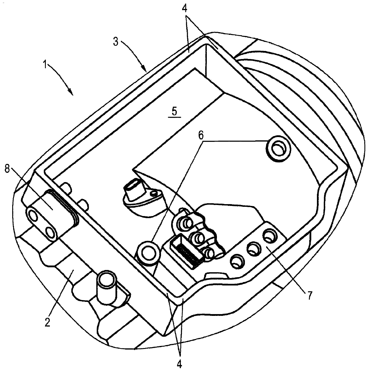
[0031] figure 1 A detailed view of the electric machine 1 is shown, the electric machine housing 2 being partly visible.

[0032] The motor housing 2 has a frame-like or groove-like section 3 with walls 4 which delimit a receiving area 5 . A coolant connection 6 is provided within the receiving area 5 for the introduction and removal of coolant for cooling the stator and / or the rotor of the electric machine 1 . Furthermore, a connection device 7 is provided within the receiving area 5 for supplying the electric machine 1 with a three-phase AC voltage and a DC voltage provided by a low-voltage battery, for example 12 volts. Furthermore, a direct voltage connection 8 is integrated in the wall 4 for supplying a direct voltage from a high-voltage battery to be converted into an alternating voltage.

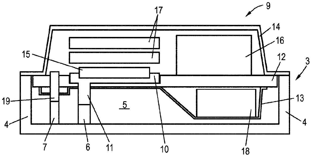
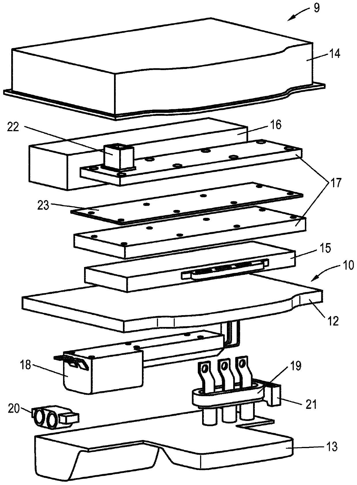
[0033] figure 1 The open side of the receiving area 5 in the installed state additionally passes through the converter device 9 (see Figure 2 to Figure 5 ), the converter device i


PUM


Abstract

The invention relates to a motor vehicle, comprising an electrical machine (1) for driving the motor vehicle (25) and a power converter device (9) for providing an alternating current for the electrical machine (1), the power converter device having a cooling device (10), the cooling device (10) having at least one cooling liquid connection point (11), which is connected to a cooling liquid interface (6) of the electrical machine (1) in a liquid-conducting manner in order to form a common cooling circuit.

Description


Claims


Application Information

Patent Timeline
Owner AUDI AG
Why Eureka
Try Eureka