Copper pipe transferring and positioning device

A positioning device and copper tube technology, which is applied to manipulators, program-controlled manipulators, manufacturing tools, etc., can solve the problems of many people needed, complicated copper tube production process, and large number of placements, and achieve the effect of improving production efficiency.

Active Publication Date: 2020-06-19
JIANGSU UNIV OF TECH
View PDF7 Cites 0 Cited by
  • Summary
  • Abstract
  • Description
  • Claims
  • Application Information

AI Technical Summary

Benefits of technology

This technology allows for efficient and automated delivery of metal tubings from an applicator machine onto another location where they will be needed again after being delivered or relocated. It uses sensors that detect if there were any flaws at certain points along its path. Once detected, this data can then be sent back downstream for analysis purposes.

Problems solved by technology

This patented technical problem addressed by this patents relates to improving cooling systems used on computers due to their poor thermal performance caused from copper material compared to traditional metal components such as aluminum or steel plating.

Method used


Image

  • Copper pipe transferring and positioning device
  • Copper pipe transferring and positioning device
  • Copper pipe transferring and positioning device

Examples


Embodiment Construction

[0012] The following will clearly and completely describe the technical solutions in the embodiments of the present invention with reference to the accompanying drawings in the embodiments of the present invention. Obviously, the described embodiments are only some, not all, embodiments of the present invention. The following description of at least one exemplary embodiment is merely illustrative in nature and in no way taken as limiting the invention, its application or uses. Based on the embodiments of the present invention, all other embodiments obtained by persons of ordinary skill in the art without creative efforts fall within the protection scope of the present invention.

[0013] It should be noted that the terminology used here is only for describing specific implementations, and is not intended to limit the exemplary implementations according to the present application. As used herein, unless the context clearly dictates otherwise, the singular is intended to include th


PUM


Abstract

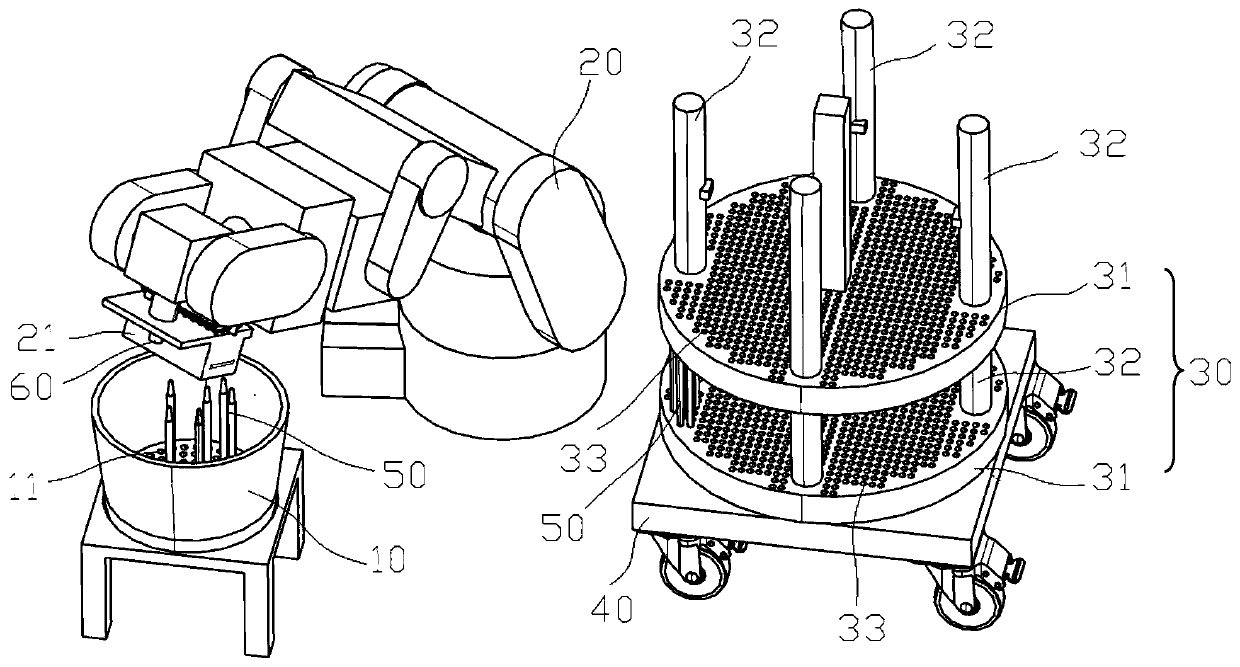
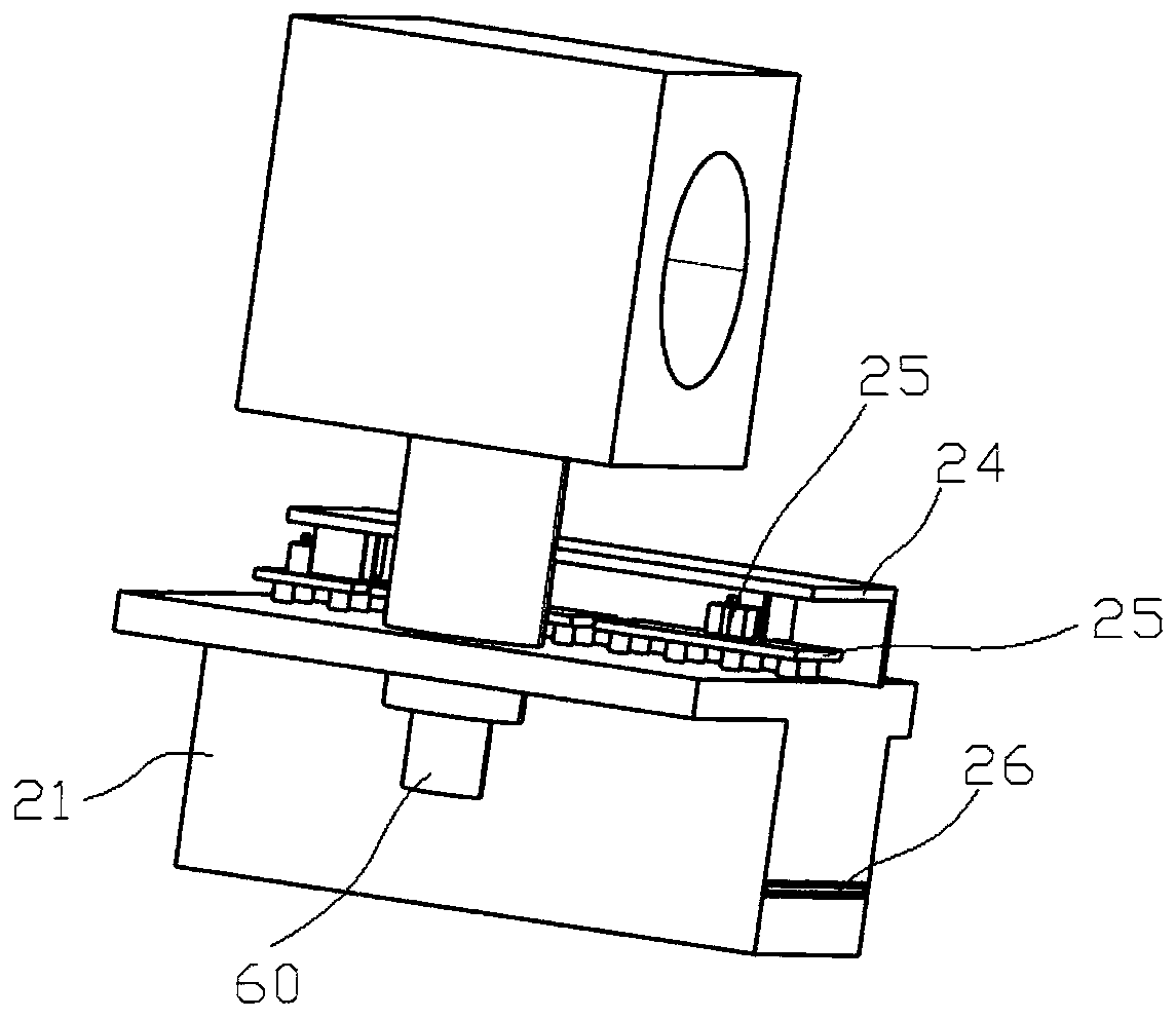
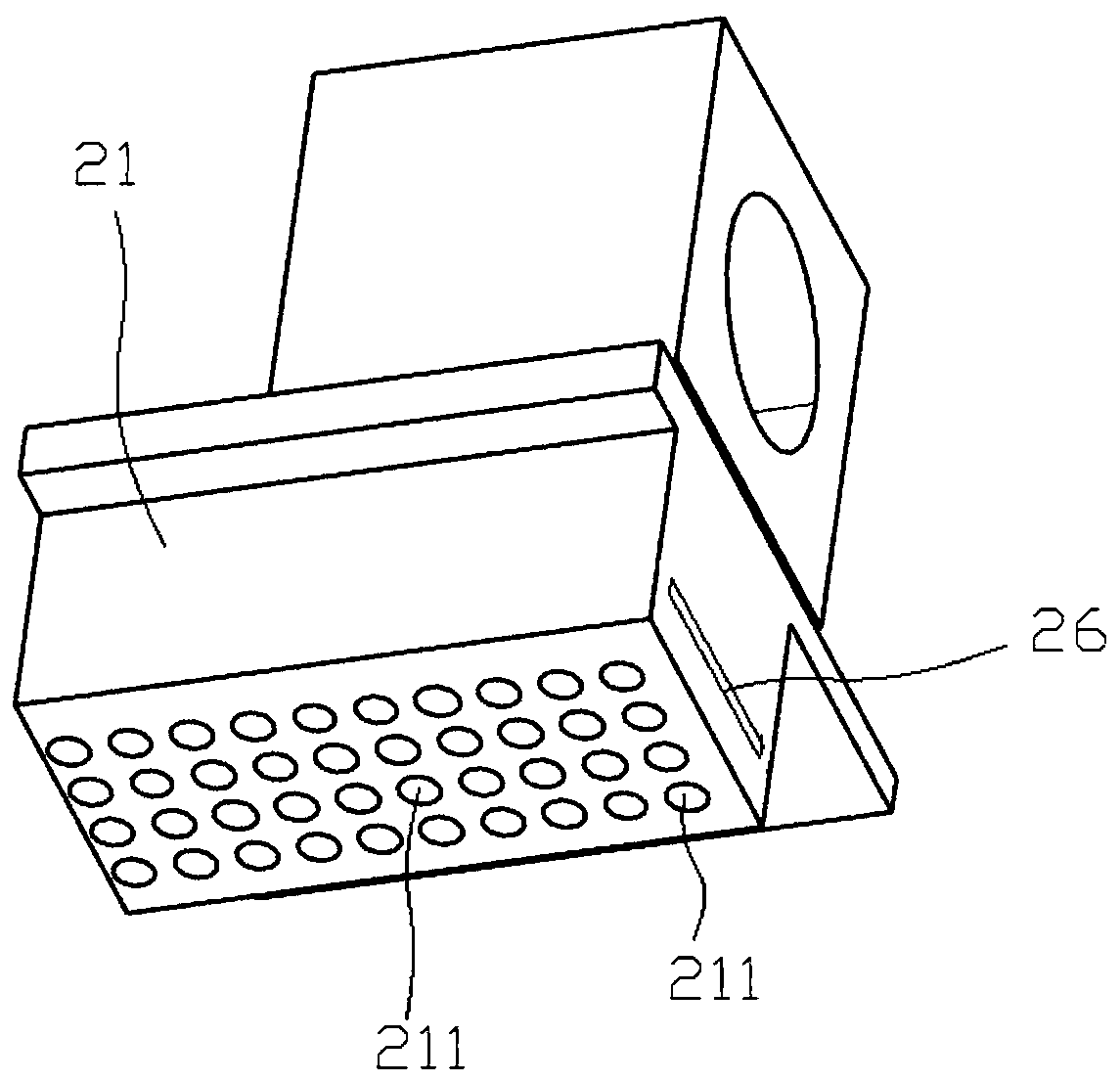
The invention relates to the technical field of copper pipe machining, in particular to a copper pipe transferring and positioning device. A plurality of copper pipes are vertically placed in a containing barrel, and a mechanical arm is transferred between the containing barrel and a positioning device; the positioning device comprises multiple layers of positioning discs in the up-down direction,and every two adjacent positioning discs are supported by a vertical positioning column; first through holes are uniformly formed in each positioning disc, the hole positions of all the positioning discs are opposite, and the multiple layers of positioning disc are detachably stacked together; the positioning disc on the bottom layer of the positioning device is placed on a movable trolley, an image sensor is fixed to an arm body of the mechanical arm, the mechanical arm transfers the copper pipes in the containing barrel into the positioning device, the two ends of each copper pipe are limited and fixed in the corresponding first through holes of the upper and lower adjacent positioning discs, the mechanical arm moves to the upper portion of the containing barrel and grabs the copper pipes in the grabbing barrel and moves to the positioning device and puts the copper pipes into the first through holes in the positioning discs, the whole process achieves fully-automatic transfer of the copper pipes, and the production efficiency is greatly improved.

Description


Claims


Application Information

Patent Timeline
Owner JIANGSU UNIV OF TECH
Why Eureka
Try Eureka