System for electric vehicle integrated with road

A technology for vehicles and roads, applied in the field of current supply systems, can solve problems such as difficulty in realization, cost, and infeasibility, and achieve the effects of reducing assembly costs, reducing manufacturing costs, and compact structures

Active Publication Date: 2020-06-23
VOLKSWAGEN AG
View PDF7 Cites 0 Cited by
  • Summary
  • Abstract
  • Description
  • Claims
  • Application Information

AI Technical Summary

Benefits of technology

This patented technology reduces electricity loss during operation by reducing impedance between different parts or zones within the system. It also improves efficiency when connecting wires with multiple protection devices. Additionally, there may include features like insulation on certain areas of the cable to further reduce energy lost due to short circuits. Overall, this technical effect helps improve overall performance and reliability of the systems used in vehicles such as fork lift trucks.

Problems solved by technology

Technological Problem addressed in this patented technical problem relates to improving safety during car operations while minimizing interference between electromagnetic waves generated due to other objects like cables installed underground near bus lines or equipment mounted at specific points along their length.

Method used


Image

  • System for electric vehicle integrated with road
  • System for electric vehicle integrated with road
  • System for electric vehicle integrated with road

Examples


Embodiment Construction

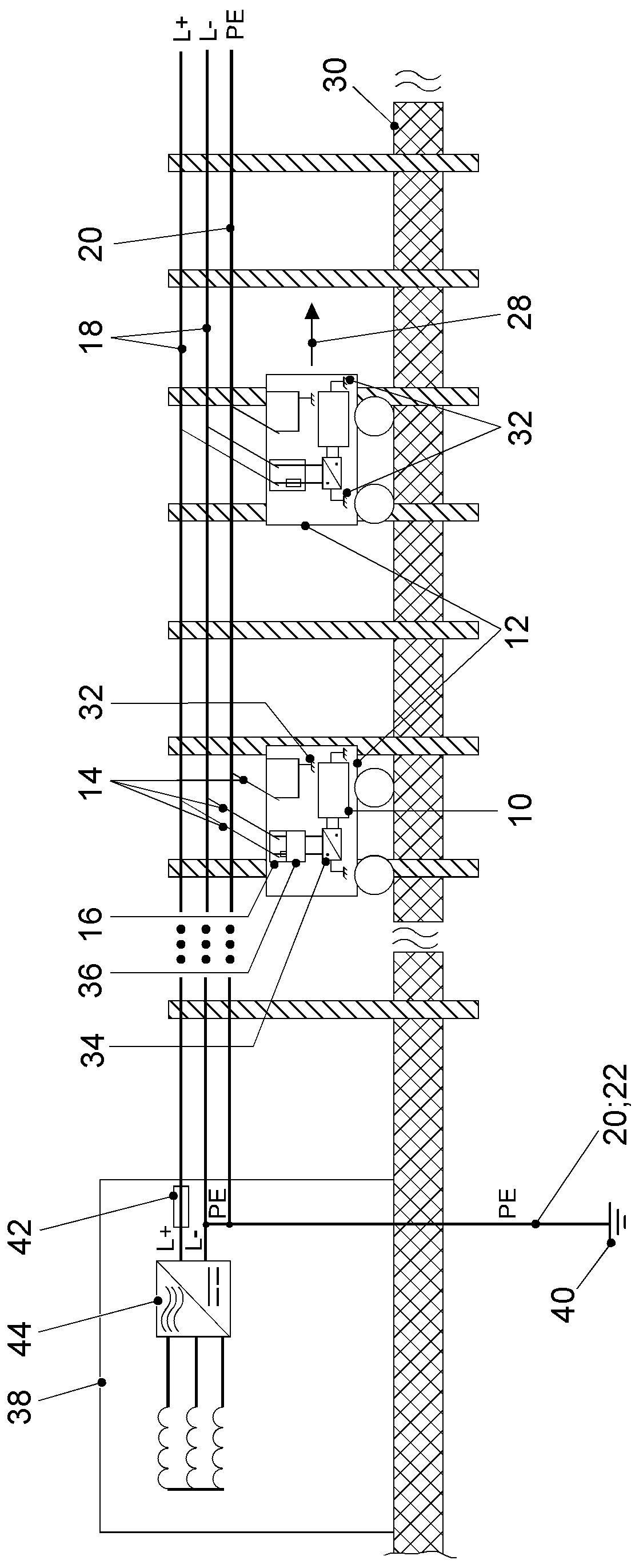
[0051] figure 1 A first embodiment variant of a system for an electric vehicle is shown. The system includes a substation 38 with a rectifier 44 and an overcurrent protection device 42 associated with the positive operating current conductor 18 . A first embodiment variant corresponds to a TN-C system, in which the negative operating current conductor 18 (neutral conductor) is designed identically to the first protective conductor 20 in at least a partial region. In addition to the first protective conductor 20 , a second protective conductor 22 runs parallel to the direction of travel 28 in the soil layer of the running track 30 . The second protective conductor 22 is insulated in particular in order to avoid stray currents (streustrom, sometimes referred to as stray currents) into the soil layer. The first protective conductor 20 and the second protective conductor 22 converge at least in the substation 38 and are connected to service ground 40 . Furthermore, the first embod


PUM


Abstract

The present invention relates to a system for an electric vehicle integrated with a road. Specifically, the present invention relates to a system for energy supply of an electric vehicle, which is innovatively solved by protective measures against electric shocks of vehicles running on electric current. The related design of the system is a TN-C- system, TN-S- system and TN-C-S- system. The systemis configured in a manner that: an additional second protective conductor (22) is provided, which is connected parallel to a first protective conductor (20), or a trolley wire includes two operatingcurrent conductors (18), at least one protective conductor (20) is provided, a vehicle (12) can be connected to the trolley wire through a first current collector (14) and is connected to the protective conductor (20) via the second current collector (14), and the second current collector (14) is connected to at least one potential balance (32) of the vehicle (12).

Description


Claims


Application Information

Patent Timeline
Owner VOLKSWAGEN AG
Why Eureka
Try Eureka