Dedusting equipment and using method thereof

A technology of dust removal equipment and dust removal chamber, which is applied in the field of dust removal equipment and foundry dust removal equipment, can solve the problems of reduced work efficiency of dust collectors, forgetting to turn off dust collectors, useless power of dust collectors, etc., and achieves simple improvement, simplified operation, and reduced energy consumption. Effect

Pending Publication Date: 2020-08-11
KOCEL STEEL
View PDF0 Cites 0 Cited by
  • Summary
  • Abstract
  • Description
  • Claims
  • Application Information

AI Technical Summary

Benefits of technology

This technology helps improve cleanliness by removing tiny particles from surfaces that may be harmful or even fatal if they shouldn't get on them during production processes. It also reduces power usage compared to traditional methods while maintaining its effectiveness over time.

Problems solved by technology

The technical problem addressed in this patented text relates to improving the performance and lifespan of an industrial plant without generating excessive amounts of metal powder (PM) due to environmental concerns such as smoking hazards caused by burning coal). Existing methods involve manual intervention with filters used to remove unwanted particles, but they have limitations like being too bulky and requiring frequent maintenance.

Method used


Image

  • Dedusting equipment and using method thereof

Examples


Embodiment Construction

[0022] In order to facilitate understanding of the present invention, the present invention will be more fully described below in conjunction with specific embodiments and with reference to related drawings. Preferred embodiments of the invention are shown in the accompanying drawings. However, the present invention can be embodied in many different forms and is not limited to the embodiments described herein. On the contrary, the purpose of providing these embodiments is to make the disclosure of the present invention more thorough and comprehensive.

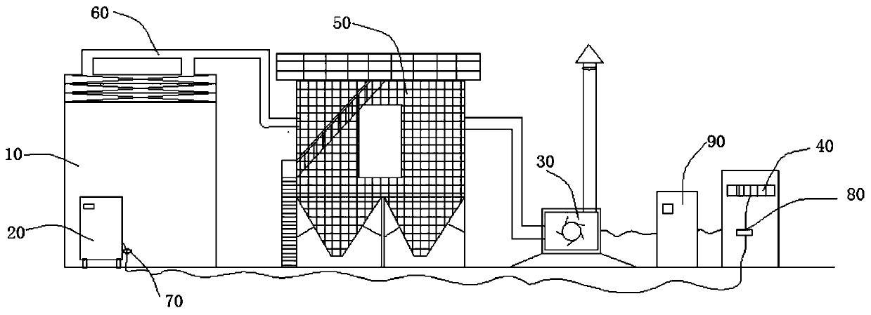
[0023] A kind of dust removal equipment, please refer to the attached figure 1 As shown, it includes a dust removal chamber 10, a gouging machine 20, a dust removal fan 30, a PLC control system 40, a dust remover 50, and a dust removal pipeline 60; The dust remover 50 communicates with the dust remover 50 through the dust removal pipeline 60, and the dust remover fan 30 communicates with the dust remover 50; , the current trans


PUM

PropertyMeasurementUnit
Current valueaaaaaaaaaa

Abstract

The invention belongs to the technical field of casting dust removal equipment, and particularly relates to dust removal equipment and a use method thereof. The dust removal equipment comprises a dustremoval chamber, an air gouging machine, a dust removal fan, a PLC control system, a dust remover and a dust removal pipeline; a gouging machine is arranged in the dust removal chamber, the dust removal chamber is communicated with the dust remover through a dust removal pipeline, and the dust removal fan is communicated with the dust remover; a current transformer is installed on the gouging machine and connected with a current transmitter, the current transmitter is connected with a PLC control system, the PLC control system is connected with a frequency converter, and the frequency converter is connected with a dust removal fan. According to the equipment, the gouging work can be effectively improved with small investment, small improvement and high return.

Description


Claims


Application Information

Patent Timeline
Owner KOCEL STEEL
Why Eureka
Try Eureka