Coal gas purification system adopting rotational flow plate gas-liquid separator

A technology of gas-liquid separator and purification system, which is applied in the direction of combustible gas purification, combustible gas purification/transformation, petroleum industry, etc., which can solve the problems of inconvenient cylinder protection treatment and inconvenient automatic discharge treatment of ammonium sulfate mother liquor, so as to improve the convenience performance, ensure integrity, and reduce leakage

Inactive Publication Date: 2021-03-19
中琉科技有限公司
View PDF5 Cites 0 Cited by
  • Summary
  • Abstract
  • Description
  • Claims
  • Application Information

AI Technical Summary

Benefits of technology

This patented technology helps improve the efficiency of clean systems used on diesel engines without causing leaks or other issues such as excessive pressure loss caused by poor lubrication. Its technical effects include improved safety features like automatic shutdowns, reduced maintenance costs associated therewith, enhanced fuel economy benefits from efficient utilization of nitrogen oxide emissions reduction catalyst (NAC), increased engine performance, and better overall vehicle design quality standards.

Problems solved by technology

This patented technical problem addressed by these inventors relates to improving the functionality or convenience of conventional coal-gas purifying devices that require manual intervention from users who may accidently release harmful gases such as nitrogen oxide (NOx) through leaks caused by poor connections between an air supply valve and an exhaust tube. Additionally, current methods involve difficult maintenance procedures involving complicated parts like filters and other equipment, making them less reliable over time.

Method used


Image

  • Coal gas purification system adopting rotational flow plate gas-liquid separator
  • Coal gas purification system adopting rotational flow plate gas-liquid separator
  • Coal gas purification system adopting rotational flow plate gas-liquid separator

Examples


Embodiment Construction

[0025] The technical solutions in the embodiments of the present invention will be clearly and completely described below with reference to the accompanying drawings in the embodiments of the present invention. Obviously, the described embodiments are only a part of the embodiments of the present invention, but not all of the embodiments. Based on the embodiments of the present invention, all other embodiments obtained by those of ordinary skill in the art without creative efforts shall fall within the protection scope of the present invention.

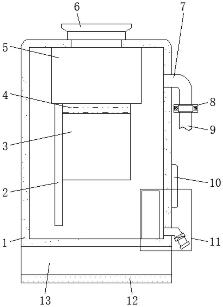
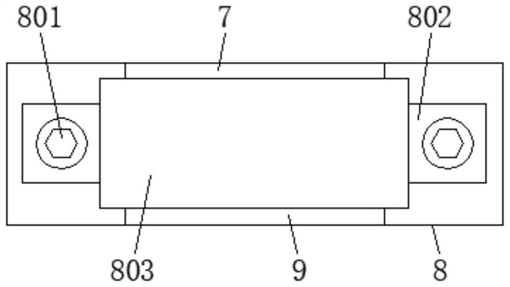
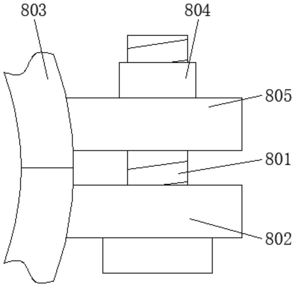
[0026] see Figure 1-5 , an embodiment provided by the present invention: a gas purification system using a cyclone plate gas-liquid separator, comprising a cylinder 1, a lower end conduit 3, a cyclone plate 4, a cyclone separation chamber 5 and an exhaust port 6, A swirl separation chamber 5 is installed at the central position of the top of the cylinder body 1, and a swirl plate 4 is arranged at the central position of the bottom end o


PUM


Abstract

The invention discloses a coal gas purification system adopting a rotational flow plate gas-liquid separator. The coal gas purification system comprises a cylinder body, a lower end guide pipe, the rotational flow plate, a rotational flow separation chamber and an exhaust port, the rotational flow separation chamber is installed in the center of the top of the cylinder body, and a rotational flowplate is arranged in the center of the bottom end of the rotational flow separation chamber; a lower end guide pipe is arranged at the end, away from the rotational flow separation chamber, of the rotational flow plate, a downcomer is fixed to the bottom end of the rotational flow separation chamber on one side of the lower end guide pipe, the exhaust port is formed in the center of the top end ofthe cylinder body, the bottom end of the exhaust port extends into the cylinder body and communicates with the top end of the rotational flow separation chamber, and a gas receiving port is formed inthe outer wall of one side of the cylinder body; and one end of the gas receiving port extends into the cylinder body, and an air injection pipe is installed at the end, away from the cylinder body,of thegas receiving port. According to the invention, the phenomenon of leakage during gas injection of the purification system is reduced, the convenience of the purification system during use is improved, and the integrity of the barrel during use of the purification system is ensured.

Description


Claims


Application Information

Patent Timeline
Owner 中琉科技有限公司
Why Eureka
Try Eureka