Iron element control method for martensitic stainless steel 2Cr13 blade

A martensitic stainless steel, control method technology, applied in the direction of manufacturing tools, furnace types, furnaces, etc., can solve problems such as failure to achieve product accuracy, method of controlling chemical content, cumbersome operation, failure to form component content standards, etc.

Pending Publication Date: 2021-07-09
赛普工业研究院(安阳)有限公司
View PDF5 Cites 0 Cited by
  • Summary
  • Abstract
  • Description
  • Claims
  • Application Information

AI Technical Summary

Problems solved by technology

These two methods can effectively reduce the ferrite content, but when manufacturing products with high toughness, none of the existing methods can meet the precision required by the

Method used


Image

  • Iron element control method for martensitic stainless steel 2Cr13 blade
  • Iron element control method for martensitic stainless steel 2Cr13 blade

Examples


Embodiment Construction

[0058] A ferrite control method for a martensitic stainless steel 2Cr13 blade of the present invention will be further described in detail below in conjunction with the accompanying drawings.

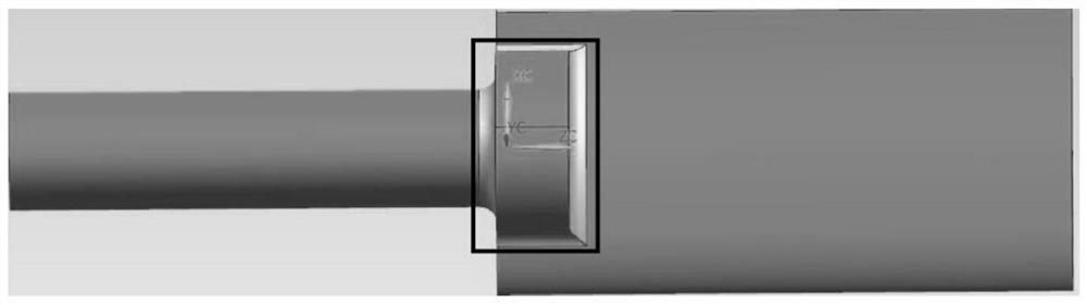
[0059] combined with Figure 1-2 , the working principle of the present invention:

[0060] The present invention mainly controls the smelting and pouring process of step 4 and the heat treatment process of step 10 in the standard process of investment casting, and the preconditions of ferrite content control ensure the control requirements of chemical composition and mechanical properties, and its various requirements complement and complement each other. associated.

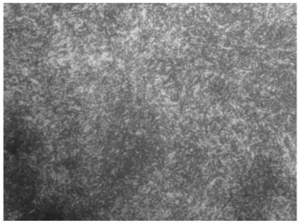
[0061] The formation mechanism of each organization is as follows:

[0062]Martensite is formed by rapid cooling and quenching of austenite. The difference between austenite and martensite is that martensite is a supersaturated solid solution of carbon in α-Fe, with a body-centered cubic structure; austenite has a face-c


PUM

PropertyMeasurementUnit
Remanenceaaaaaaaaaa

Abstract

The invention discloses an iron element control method for a martensitic stainless steel 2Cr13 blade. The iron element control method comprises the following steps of wax piece manufacturing, wax piece combining, mold shell manufacturing, smelting and pouring, shell cleaning and cutting, component testing, primary repairing, magnetic powder processing, X-ray inspection, annealing and primary correction, heat treatment (solid solution and aging treatment), internal structure detection and fine repairing. According to the iron element control method, the iron content can be effectively reduced to about 1%; an internal structure result meets the requirements, chemical components of a casting meet the requirements through detection, the mechanical properties of a body meet the requirements through detection, the surface quality of the casting is subjected to magnetic powder inspection, and a detection result meets the GB/T9444 01-level requirement; the internal quality of the casting is subjected to ray inspection, the detection result meets the requirements of GB/T 5677 and ASTM E446, and the class A, the class B, the class C and the class D discontinuously meet the first-level requirement.

Description


Claims


Application Information

Patent Timeline
Owner 赛普工业研究院(安阳)有限公司
Why Eureka
Try Eureka