Thin double-layer trunnion box structure

A trunnion box and double-layer technology, which is applied in the field of thin double-layer trunnion box structure, can solve the problem of insufficient connection between the thin trunnion box and the drum body, and achieve the goal of ensuring force, optimizing force, and ensuring mechanical properties Effect

Pending Publication Date: 2022-02-01
WUXI JULI HEAVY IND OFF
View PDF0 Cites 0 Cited by
  • Summary
  • Abstract
  • Description
  • Claims
  • Application Information

AI Technical Summary

Benefits of technology

This innovation uses two different types of forces - one acts on an object's surface while another applies pressure onto it. It achieves this through linking or holding tiny pieces together with supportive material that keeps them steady even if they get too much weight for their own strength. By doing things like adding padding between layers within the panels, we can make structures stronger without losing its shape over time. Additionally, there may be other ways to improve mechanical performance such as making certain parts stiffer at specific points along the length of the tubes instead of just keeping everything fixed down tightly. Overall, these technical improvements help create more reliable and durable machines.

Problems solved by technology

This patented problem addressed in the technical solution described by the inventors relates to how an expanded lorry can have its own weight without being limited on one side or requiring extra equipment for other purposes such as adding another carriageway when needed.

Method used


Image

  • Thin double-layer trunnion box structure
  • Thin double-layer trunnion box structure

Examples


Embodiment Construction

[0014] In order to deepen the understanding of the present invention, the present invention will be described in further detail below in conjunction with the accompanying drawings and embodiments, which are only used to explain the present invention and do not limit the protection scope of the present invention.

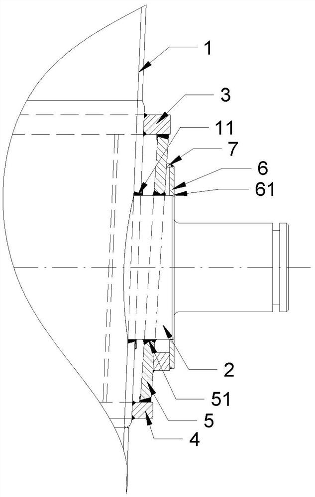
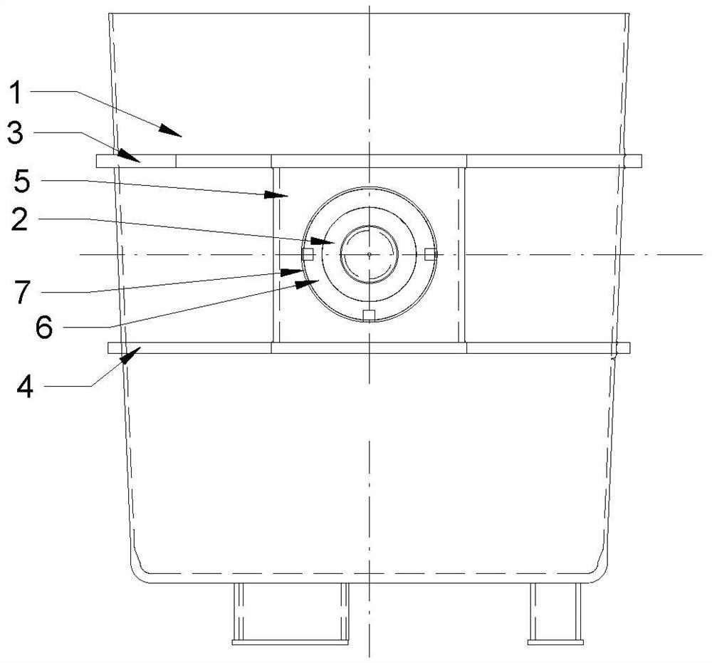
[0015] A thin double-layer trunnion box structure, which includes a barrel body 1 and trunnion boxes 2 arranged on both sides of the barrel body 1, the upper and lower sides of the trunnion box 2 are respectively provided with an upper waist hoop 3, a lower waist hoop 4, and an upper waist hoop 4. The hoop 3 and the lower waist hoop 4 are fixed on the barrel body 1 respectively; the upper waist hoop 3 and the lower waist hoop 4 are welded with a vertical plate 5, and the front side of the vertical plate 5 is provided with a panel 6, and the panel 6 is fixed to the vertical plate through the ring plate 7 5; the limit hole 61 passing through the center of the panel 6 of th


PUM


Abstract

The invention provides a thin double-layer trunnion box structure which can ensure the mechanical property of the thin trunnion box structure. The structure comprises a bucket body and trunnion boxes arranged on the two sides of the bucket body, an upper waist hoop and a lower waist hoop are arranged on the upper sides and the lower sides of the trunnion boxes respectively, and the upper waist hoop and the lower waist hoop are fixed to the bucket body in a surrounding mode; a vertical plate is welded between the upper waist hoop and the lower waist hoop, a panel is arranged on the front side of the vertical plate, and the panel is fixed on the vertical plate through a ring plate; and each trunnion box penetrates through the limiting hole in the center of the panel, a supporting hole in the center of the vertical plate and a mounting hole of the bucket body, and the outer side wall of the trunnion box is connected with the limiting hole and the supporting hole in a welded mode and is in clearance fit with the limiting hole.

Description


Claims


Application Information

Patent Timeline
Owner WUXI JULI HEAVY IND OFF
Why Eureka
Try Eureka