Biogas carbon reduction coupled biogas slurry pollution reduction device and method based on biogas circulating fermentation

A circulating biogas technology, applied in the field of environment and energy, can solve the problems of poor treatment effect, poor biodegradability, and low mass transfer efficiency, and achieve the effects of improving electrolysis efficiency, increasing the calorific value of biogas, and increasing methane content

Pending Publication Date: 2022-06-03
UNIV OF SCI & TECH BEIJING +1
View PDF0 Cites 1 Cited by
  • Summary
  • Abstract
  • Description
  • Claims
  • Application Information

AI Technical Summary

Benefits of technology

This patented technology describes various technical means such as improving the performance of electronic devices (Electronics), decreasing environmental impact caused by harmful substances released from wastewater treatment plants during combustion processes, producing valuable chemical products like ammonia fertilizers, and integrally incorporated fuel cells called oxynitride generators (ONC). These technologies aim to solve issues related to disposal of these wastes without causing negative side effects on their environment' s ecosystem.

Problems solved by technology

This patented technical problem addressed in this patents relates to improving the removal of harmful gases from combustion processes such as coal or oil fired power plants through chemical methods like oxoelecrosis (biomass conversion). Current treatments involve expensive techniques involving complicated operations, environmental concerns, and potential negative side effects associated therewith. Existing in situ purifying devices have limitations in terms of their ability to efficiently convert hydrocarbon compounds into carbon dioxide without causing damage during processing.

Method used


Image

  • Biogas carbon reduction coupled biogas slurry pollution reduction device and method based on biogas circulating fermentation
  • Biogas carbon reduction coupled biogas slurry pollution reduction device and method based on biogas circulating fermentation
  • Biogas carbon reduction coupled biogas slurry pollution reduction device and method based on biogas circulating fermentation

Examples


Embodiment 1

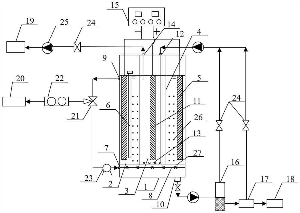
[0078] The method of biogas carbon reduction coupled with biogas slurry pollution reduction based on biogas cyclic fermentation mainly includes the following steps:

[0079] (1) Start-up stage: Inoculate digested sludge in a substrate with a 7:3 VS mixing ratio of kitchen waste and fungus chaff, so that the VS ratio of digested sludge to substrate is 1:1 to 2:1. The mixture was added to the cathode chamber 2 through the liquid-sealed feed port 6, and nitrogen was introduced to maintain the system under anaerobic conditions, and anaerobic fermentation was carried out at a temperature of 50-55 °C until the high-temperature digestion reaction cycle ended. The fermentation residue enters the solid-liquid separation unit through the fermentation residue discharge port 10;

[0080] (2) The fermentation residue is separated by the mechanical dehydration device 16 to obtain biogas slurry, which is uniformly injected into the bottom of the anode chamber 3 through the biogas slurry liquid

Embodiment 2

[0085] The difference between this example and Example 1 is that the biogas generated by the anaerobic digestion of the mixed substrate of kitchen waste and fungus chaff is cyclically injected into the lower biogas through the biogas outlet 9, the three-way diverter valve 21 and the air pump 23 in the upper part of the cathode chamber. The air inlets 7 are evenly distributed in the cathode chamber 2 through the air distribution pipes 8 with holes. During the continuous operation period of anaerobic fermentation during the biogas cycle, the CO in the biogas 2 The active hydrogen produced by the cathode is converted into methane under the action of hydrogenophilic methanogens, and the H passing through the anode chamber + It also participates in the biochemical conversion reaction; real-time monitoring of the methane concentration in the biogas, when the methane concentration in the biogas reaches more than 90%, it can enter the purified biogas storage tank 20 through the three-way

Embodiment 3

[0087] The difference between this embodiment and Embodiment 1 is that the biogas residue hydrothermal carbon 26 is made into a block with a certain shape and mechanical strength, and is filled into the cathode chamber 2 as a biological carrier (also serving as a cathode conductor), The hydrogen methanogens are attached to these hydrothermal carbon carriers through immobilized culture in advance; when the circulating biogas bubbles pass through the hydrothermal carbon layer, the flow rate of biogas decreases, which is beneficial to the CO in the biogas 2 More is dissolved and adsorbed on the hydrothermal char, where it is converted into methane by hydrogenophilic methanogens.


PUM


Abstract

The invention provides a biogas carbon reduction coupling biogas slurry pollution reduction device and method based on biogas circulation type fermentation, and belongs to the technical field of environment and energy. The device comprises an electric fermentation unit, a solid-liquid separation unit, a hydrothermal carbonization unit and a product collection unit, wherein the electric fermentation unit comprises an electric fermentation tank, a cathode chamber, an anode chamber, a cation exchange membrane and a direct-current constant-voltage power supply; according to the device, biotransformation of hydrogen-philic methanogens and electrochemical cathode reduction are coupled, biogas is circulated to an anaerobic digestion chamber, in-situ biogas biological purification is carried out, ammonia nitrogen and COD in biogas slurry are removed in an anode chamber while CO2 is reduced at a cathode to generate methane, and electron transfer and conservation rules are reasonably utilized; the biogas slurry can be used for irrigation after pollution reduction, and residual pollutants in the biogas slurry can also be adsorbed by biogas residue biochar to be further purified; the biogas residues can be prepared into hydrothermal carbon to be reused for anaerobic digestion or used as an adsorbent, so that the aims of comprehensive utilization of biogas slurry, biogas residues and biogas and CO2 emission reduction are fulfilled.

Description


Claims


Application Information

Patent Timeline
Owner UNIV OF SCI & TECH BEIJING
Why Eureka
Try Eureka