Load test device and method for test pile

A technology of load test and test device, which is applied in the test of foundation structure, sheet pile wall, building, etc., can solve the problems of time-consuming, labor-intensive and material-consuming to assemble and disassemble steel bars, and achieve flexible and changeable devices and methods, and simple and quick disassembly. Effect

Pending Publication Date: 2022-06-21
山西华冶勘测工程技术有限公司
View PDF5 Cites 0 Cited by
  • Summary
  • Abstract
  • Description
  • Claims
  • Application Information

AI Technical Summary

Benefits of technology

This patented loading testing machine uses an anchor cables that attaches it securely to metal barrels during use. It has several technical benefits over existing methods like bolting or screw-tightened connections. Its simplicity makes assembly easier compared with traditional ways while still providing enough strength against loads. Additionally, this system allows for flexibility when adding more weight without requiring extra equipment.

Problems solved by technology

This technical problem addressed during research into making better quality concrete structures involves conducting tensile stress loading experiments (TST) on small samples that have been tested under specific conditions such as temperature changes over an extended period of time without requiring complicated procedures like setting up temporary support columns between different levels of reinforcement material inside each sample being analyzed.

Method used


Image

  • Load test device and method for test pile
  • Load test device and method for test pile
  • Load test device and method for test pile

Examples


Embodiment Construction

[0030] The present invention will be further described below with reference to the accompanying drawings and specific embodiments, but it is not intended to limit the present invention.

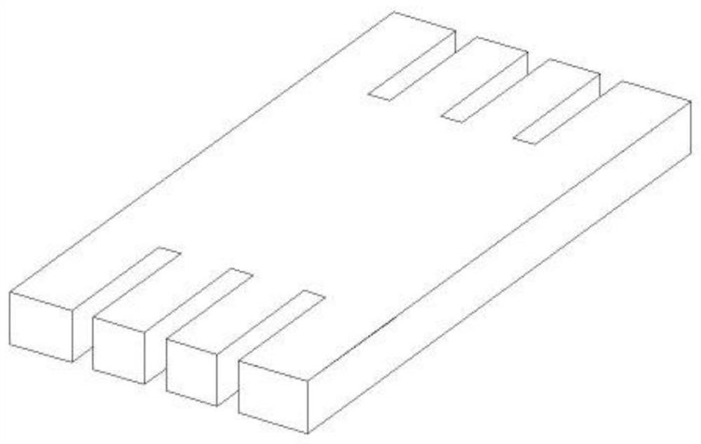
[0031] The invention describes a load test device for a test pile, comprising an anchor pile beam arranged on the test pile, and anchor plates symmetrically placed at both ends of the anchor pile beam, such as figure 1 As shown in the figure, the anchor plate includes a body, and the opposite ends of the body are symmetrically provided with a plurality of limit slots; the test device also includes a plurality of anchors and a plurality of anchor cables, and one end of the anchor cables penetrates the anchors and the limit grooves. Slots are used to fix the anchor to the anchor plate to provide vertical pressure to the test pile. The invention utilizes the anchor plate and the anchor to fix the anchor cable, and provides the vertical pressure to the test pile through the anchor pile beam, thereby


PUM


Abstract

The invention discloses a load test device for a test pile, which comprises an anchor pile beam arranged on the test pile and anchorage plates symmetrically arranged at the two ends of the anchor pile beam, each anchorage plate comprises a body, and a plurality of limiting grooves are symmetrically formed in the two opposite ends of the body; the test device further comprises a plurality of anchorage devices and a plurality of anchor cables, one ends of the anchor cables penetrate through the anchorage devices and the limiting grooves and are used for fixing the anchorage devices to the anchorage device plate so as to provide vertical bearing force for the test pile, the load test device adopts an anchor cable anchoring method to provide counter force, materials such as welding rods needed by steel bar welding are reduced, and the test efficiency is improved. And assembly and disassembly are simple, fast, time-saving and labor-saving.

Description


Claims


Application Information

Patent Timeline
Owner 山西华冶勘测工程技术有限公司
Why Eureka
Try Eureka