Gear reduction unit

a gear reduction unit and gear reduction technology, applied in mechanical equipment, transportation and packaging, gearboxes, etc., can solve the problems of reducing efficiency, reducing efficiency, and reducing efficiency, and achieves high contact ratio, double torque capacity, and wide use.

Inactive Publication Date: 2005-02-10
FLEYTMAN YAKOV
View PDF20 Cites 24 Cited by
  • Summary
  • Abstract
  • Description
  • Claims
  • Application Information

AI Technical Summary

Benefits of technology

The present invention provides a simpler and more efficient way to adjust the gear ratios on both left-handed and right-handed gears. By attaching two different types of right angle gears together, this can increase its torque capacity without making them bigger than usual. Additionally, by changing these gears with parallel shafts, they are easier to manufacture and assemble into various gearboxes that work at different speeds.

Problems solved by technology

The technical problem addressed in this patent is how to improve the performance of right angle gear transmission systems without making them bigger and less efficient than traditional designs.

Method used


Image

  • Gear reduction unit
  • Gear reduction unit
  • Gear reduction unit

Examples


Embodiment Construction

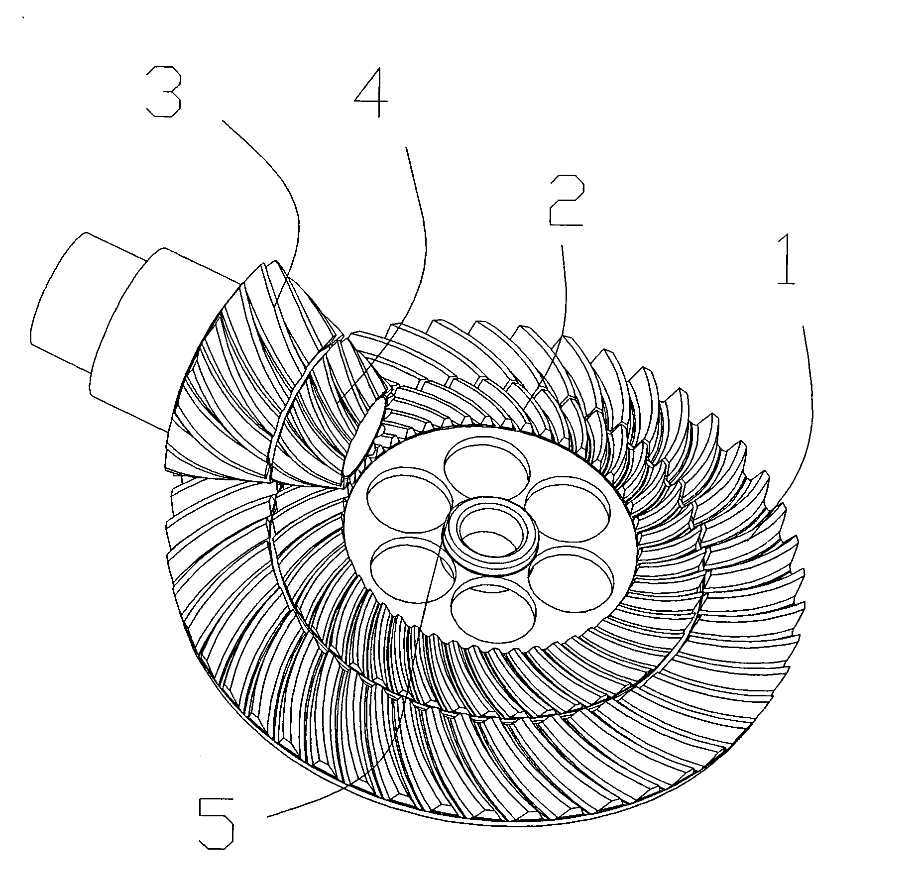
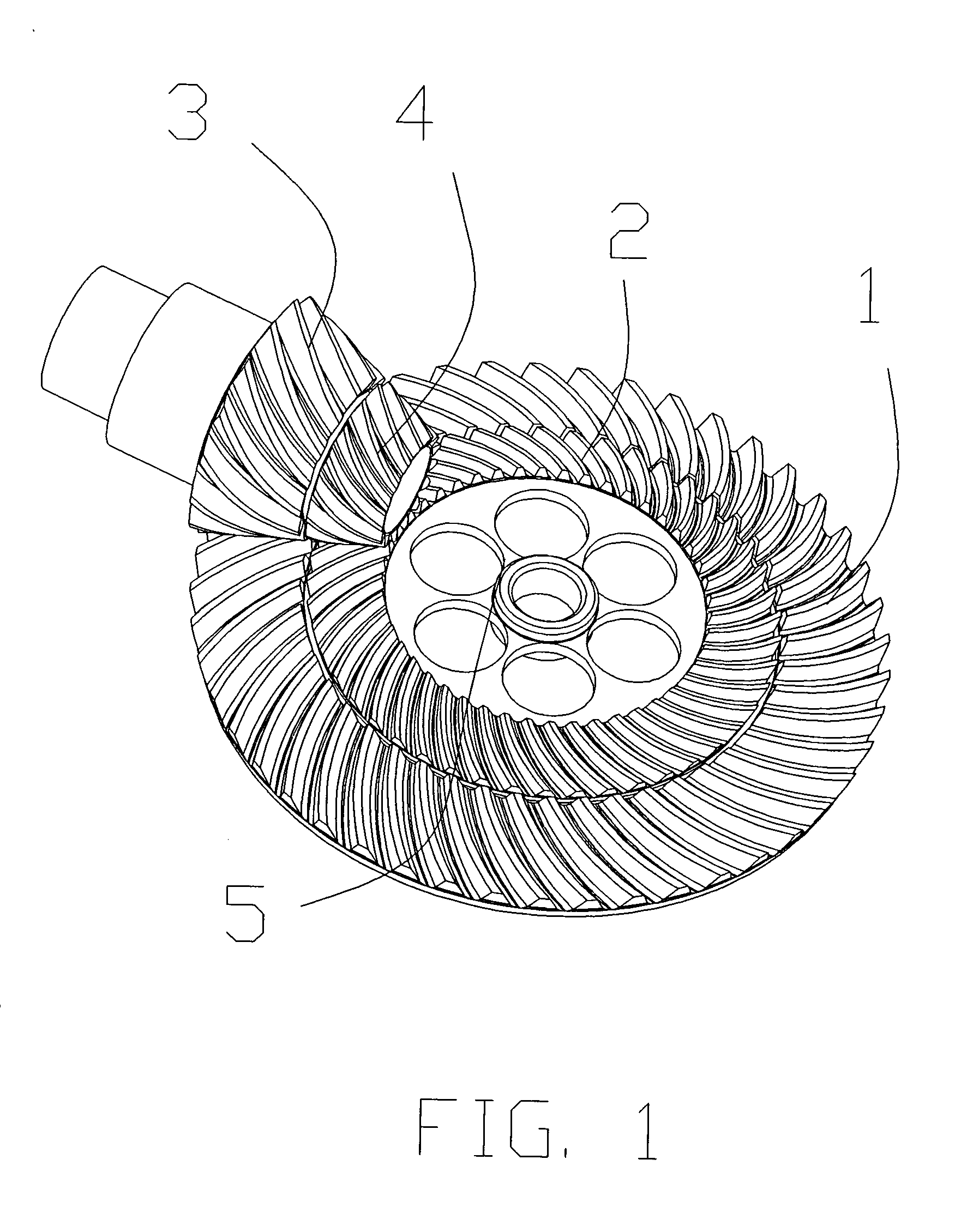
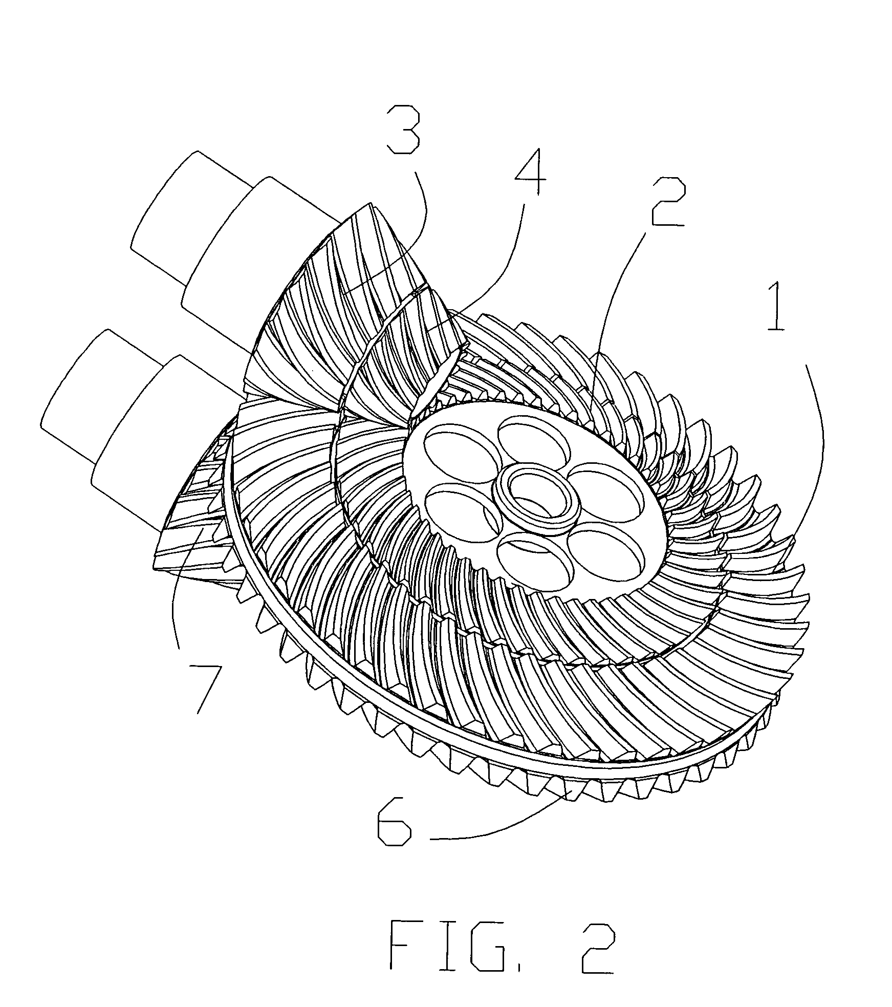
[0036] The following discussion relating to FIGS. 1-28 provides a detailed description of the unique gear reduction unit which can be utilized with the present invention. More torque capacity is the main advantage for using the right angle gears. For various torque capacities and design requirements different right angle gear sets could be used. Spiral bevel gears and hypoid gears are bevel type right angle gears. In pair of gears a pinion is a gear with less or equal number of gear teeth. Gears shown in schematic view could be bevel type (spiral bevel or hypoid) or face gear with regular worm or enveloping worm having threads with less than 90 degrees of revolution.

[0037]FIG. 1 is an isometric view of coaxially mounded first spiral bevel 1 and second spiral bevel gears 2 gears in mesh with coaxially mounded first pinion 3 and second pinion 4. Gears 1 and 2 are connected to each other. Output member 5 of gears 1 and 2 may be linked to a source of mechanical energy or to a load. Pinion


PUM


Abstract

A gear reduction unit is provided with a unique combination of right angle gears with means for distinct connection of pinions or gears with an independent shaft. The gear reduction unit has many variations with different types of right angle gears, according with the desired numbers of ratios and torque and size requirements. The gear reduction unit is more efficient, quite and more compact than conventional parallel shaft or planetary systems which have been typically used in power regulating transmissions. The gear reduction unit of the present invention is easily manufactured.

Description


Claims


Application Information

Patent Timeline
Owner FLEYTMAN YAKOV
Why Eureka
Try Eureka