Method for designing a digital abutment for dental implant

Inactive Publication Date: 2009-04-30
POU BIOTECH
View PDF11 Cites 48 Cited by
  • Summary
  • Abstract
  • Description
  • Claims
  • Application Information

AI Technical Summary

Benefits of technology

[0006]The present invention has been accomplished under the circumstances in view. It is one object of the present invention to provide

Problems solved by technology

However, because of aesthetic considerations, bite accuracy, or poor alveolar bone condition, the result of implant planning may be not optimal.
However, selection of an abutment after dental implant planning using conventional techniques may encounter certain problems.
A dentist is unable select the ideal abutment that fits the bite angle perfectly based on t

Method used


Image

  • Method for designing a digital abutment for dental implant
  • Method for designing a digital abutment for dental implant
  • Method for designing a digital abutment for dental implant

Examples


Embodiment Construction

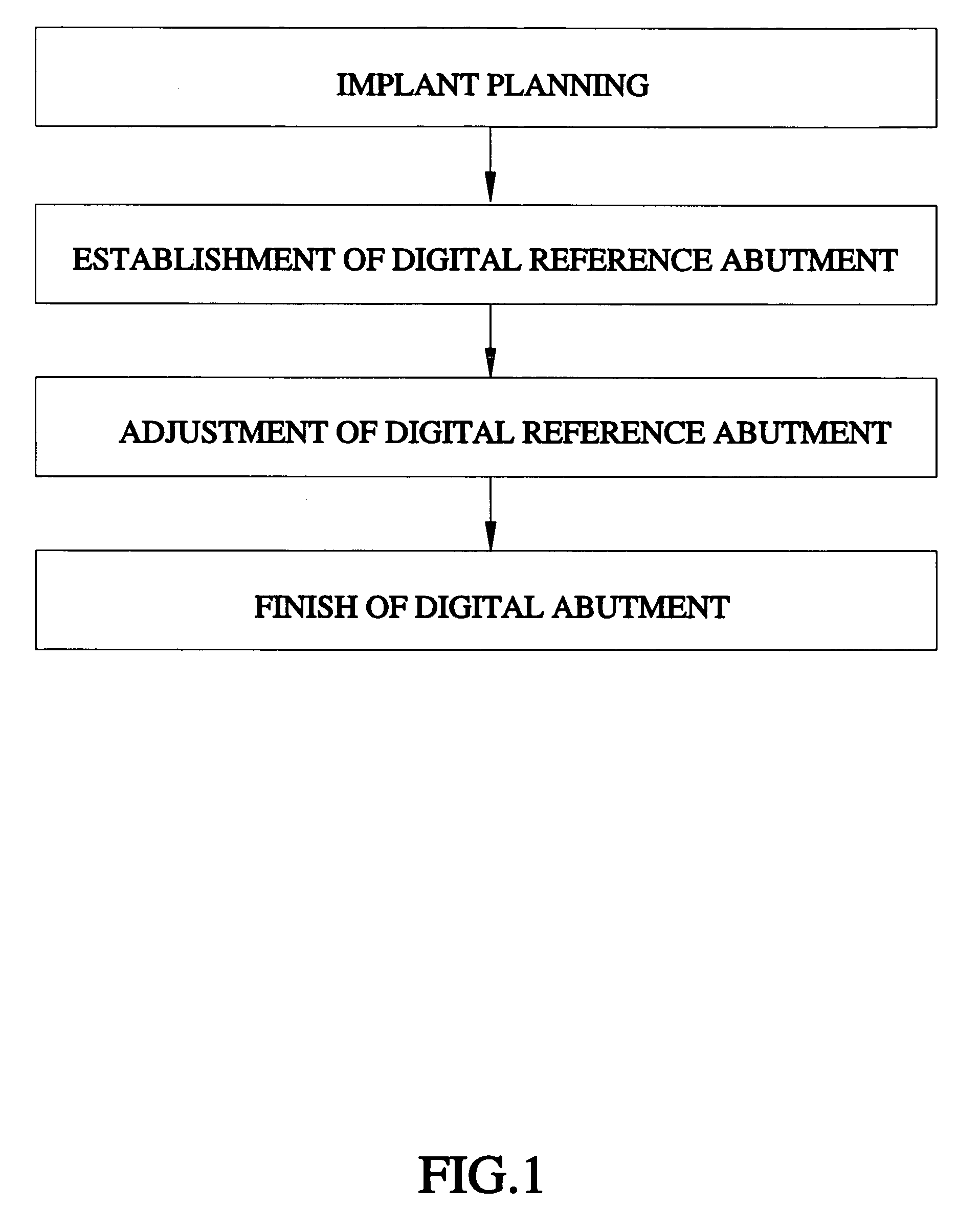
[0021]Referring to FIG. 1, a method for designing a digital abutment for a dental implant fixture in accordance with a first embodiment of the present invention includes the steps of:

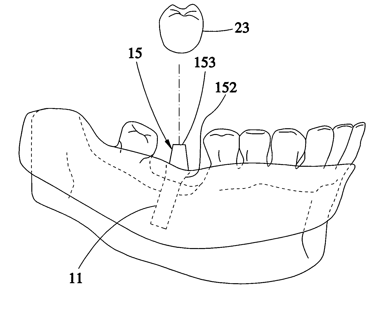
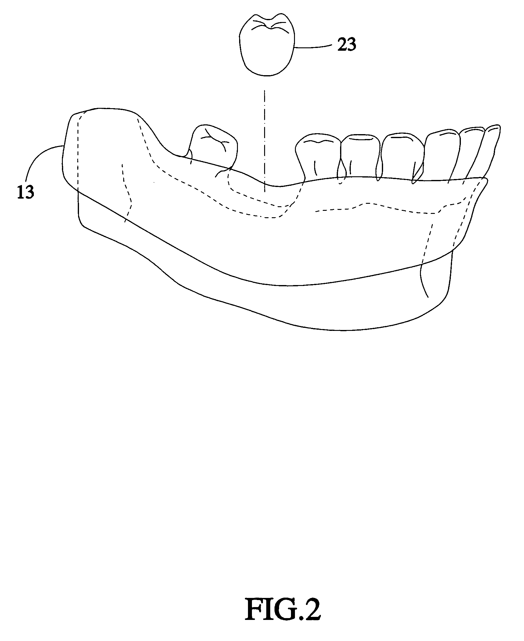
[0022]a) Implant planning: As shown in FIGS. 2 and 3, initiate implant planning based on the digital data obtained from the patient and loaded into the computer system to enable the implant fixture 11 (see FIG. 4) to be implanted at the implant site in the best position. The computer has the data of the digital oral cavity model of the patient. The data of the digital oral cavity model includes a digital gum 13 and a digital crown 23. The digital gum 13 and the digital crown 23 can be loaded from a digital database (not shown) of the computer system. Alternatively, the digital data can be loaded by means of scanning a gum / crown model made subject to the configuration of the oral cavity of the patient.

[0023]b) Establishment of digital reference abutment: As shown in FIGS. 4˜6, a digital reference abutment


PUM


Abstract

A method for designing a digital abutment for a dental implant includes the steps of: a) implant planning where implant planning is initiated based on digital data obtained from the patient and loaded into a computer system to enable an implant fixture to be implanted at the implant site in the best position, b) establishment of digital reference abutment where a digital reference abutment is established at the implant site and positioned on the implant fixture, c) adjustment of the digital reference abutment where the digital reference abutment has a subgingival part and a supragingival part at the top side of the subgingival part, and the angle between the subgingival part and the supragingival part is adjusted based on the best prosthesis position, and d) finish of digital abutment where the digital reference abutment becomes a digital abutment for placement after the adjustment.

Description


Claims


Application Information

Patent Timeline
Owner POU BIOTECH
Why Eureka
Try Eureka