Piezoelectric element, liquid ejecting head, and liquid ejecting apparatus
- Summary
- Abstract
- Description
- Claims
- Application Information
AI Technical Summary
Benefits of technology
Problems solved by technology
Method used
Image

Examples
embodiment 1
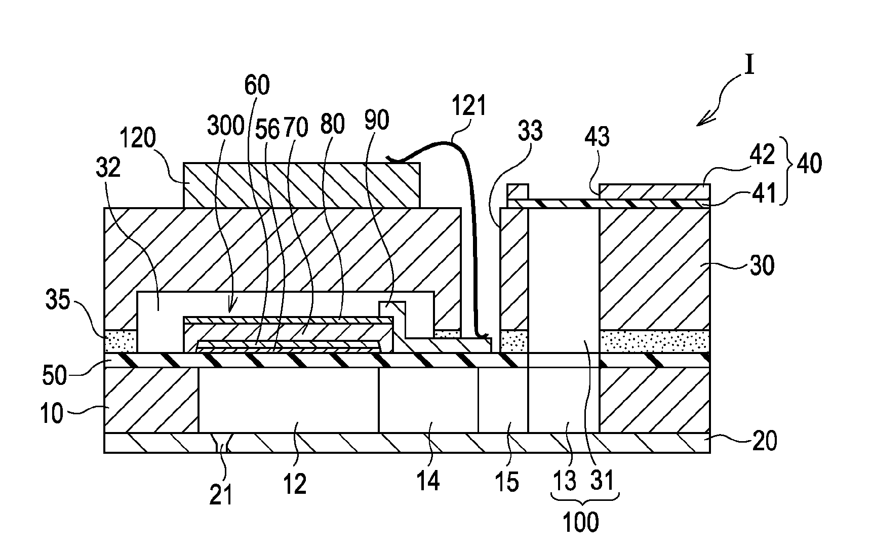
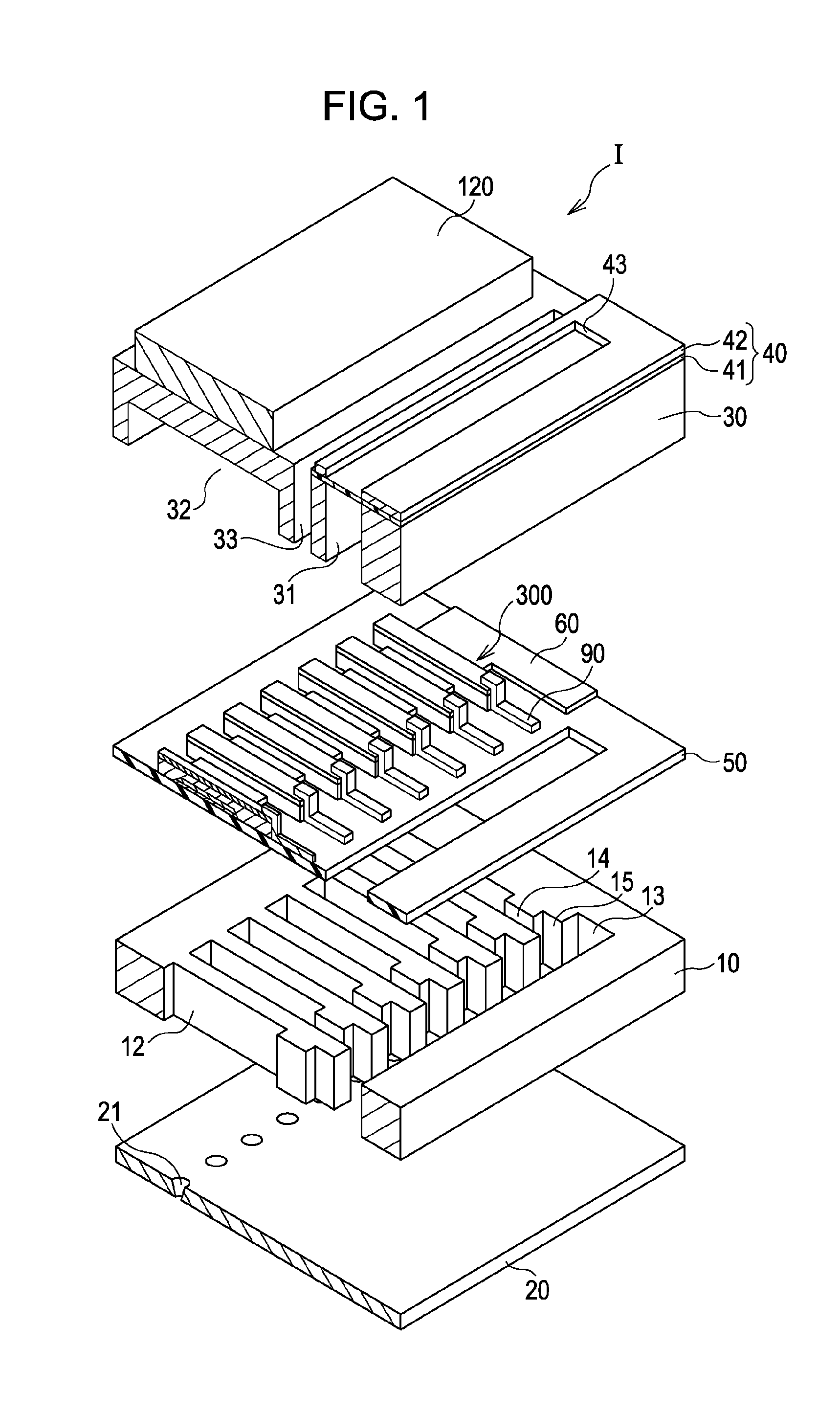
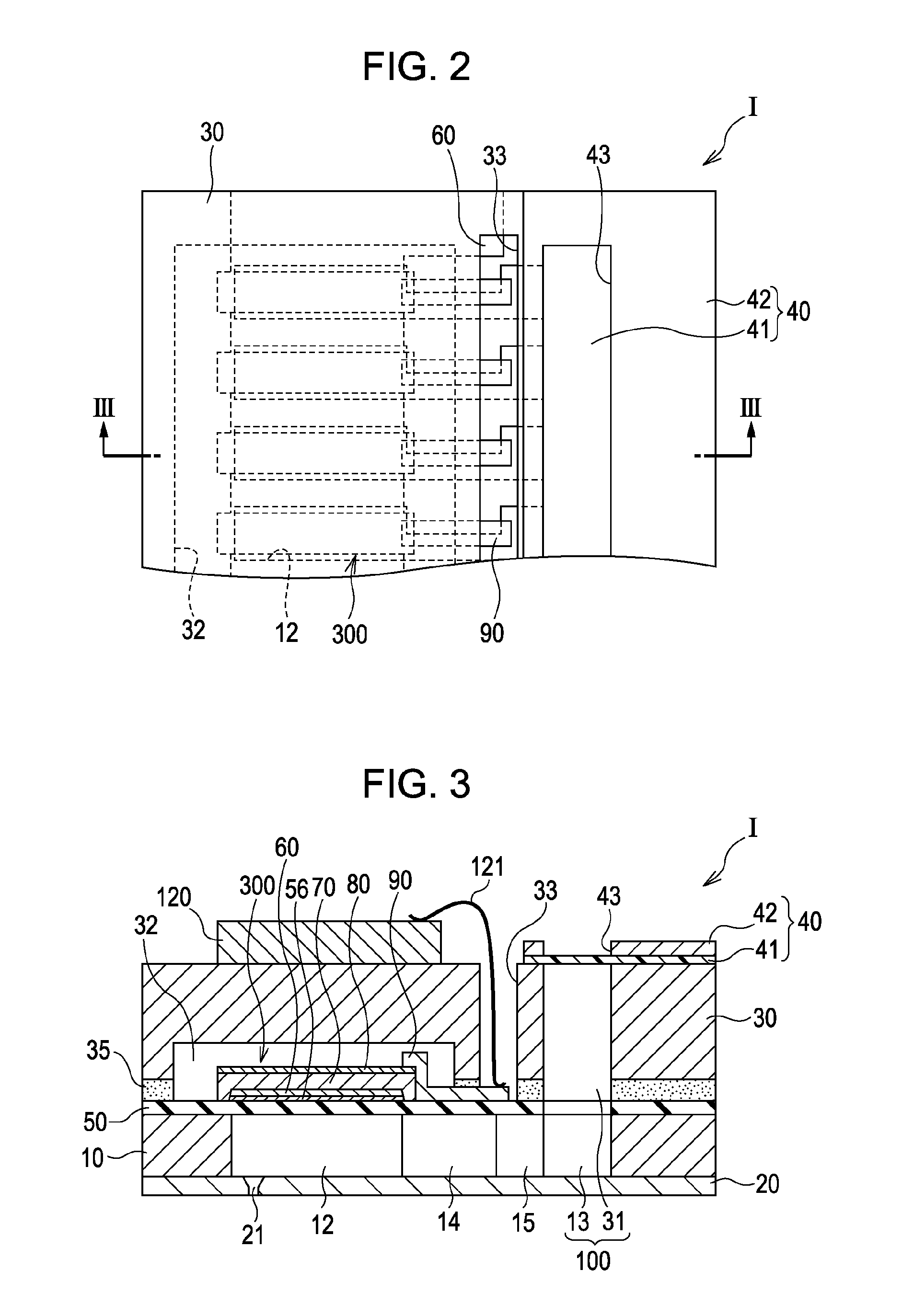
[0029]FIG. 1 is an exploded perspective diagram illustrating a schematic constitution of an ink jet recording head, which is an example of the liquid ejecting head according to Embodiment 1 of the invention, FIG. 2 is a plan view of FIG. 1, and FIG. 3 is a cross-sectional diagram taken along line III-III of FIG. 2. As illustrated in FIGS. 1 to 3, in this embodiment, a flow channel substrate 10, which is a silicon single crystal substrate, is covered on either side with an elastic film 50, which is made of silicon dioxide.
[0030]The flow channel substrate 10 has several pressure chambers 12 arranged in parallel. Either one of the regions of the flow channel substrate 10 extending outside the longitudinal ends of the pressure chambers 12 has a communicating space 13, and the communicating space 13 communicates with the pressure chambers 12 via ink supply paths 14 and communicating paths 15, both formed in correspondence with the pressure chambers 12. The communicating space 13 also commun
example 1
[0068]First, a silicon dioxide (SiO2) film having a thickness of 1000 nm was formed on the surface of a silicon (Si) single crystal substrate by thermal oxidation. Then, a titanium oxide film having a thickness of 40 nm was formed on the SiO2 film by direct-current (DC) sputtering and thermal oxidation. Then, a platinum film having a thickness of 130 nm (the first electrode 60) was formed on the titanium oxide film.
[0069]Subsequently, a piezoelectric layer 70 was formed on the first electrode 60 by spin coating. The procedure was as follows.
[0070]First, a precursor solution was prepared by mixing the following solutions in amounts satisfying a molar composition K:Na:Nb:Bi:Fe=0.5:0.5:1:0.01:0.01: potassium 2-ethylhexanoate in 1-butanol, sodium 2-ethylhexanoate in 1-butanol, niobium 2-ethylhexanoate in 1-butanol, bismuth 2-ethylhexanoate in octane, and iron 2-ethylhexanoate in xylene.
[0071]The obtained precursor solution was dropped onto the substrate having the titanium oxide film and t
example 2
[0073]A piezoelectric element 300 was made in the same way as in Example 1 except that the amounts of the solutions (potassium 2-ethylhexanoate in 1-butanol, sodium 2-ethylhexanoate in 1-butanol, niobium 2-ethylhexanoate in 1-butanol, bismuth 2-ethylhexanoate in octane, and iron 2-ethylhexanoate in xylene) were changed to satisfy a molar composition K:Na:Nb:Bi:Fe=0.5:0.5:1:0.03:0.03.
PUM
 Abstract
Description
Claims
Application Information
 - R&D Engineer
- R&D Manager
- IP Professional
- Industry Leading Data Capabilities
- Powerful AI technology
- Patent DNA Extraction
Browse by: Latest US Patents, China's latest patents, Technical Efficacy Thesaurus, Application Domain, Technology Topic.
© 2024 PatSnap. All rights reserved.Legal|Privacy policy|Modern Slavery Act Transparency Statement|Sitemap