Reversibly adhesive thermal interface material

a technology of thermal interface material and adhesive, which is applied in the direction of electrical apparatus construction details, semiconductor/solid-state device details, transportation and packaging, etc., can solve the problems of voids at the interface, excessive heat generation during device operation, and degrade device performan

Active Publication Date: 2012-07-19
IBM CORP
View PDF9 Cites 25 Cited by
  • Summary
  • Abstract
  • Description
  • Claims
  • Application Information

AI Technical Summary

Benefits of technology

This patent describes different ways for creating a thermal interface material with good thermal conductivity and electrical properties. It involves adding a special type of chemical called a redox-cross-linking agent into a specific part of the material. These agents can be added either beforehand or afterward on top of the material. By combining these two parts together, there will be a strong bond between them. Overall, this technology allows for efficient use of materials while maintaining their desired functions.

Problems solved by technology

The technical problem addressed by this patent is how to improve the efficiency of removing and rebuilding thermal interface materials used in electronic product applications while minimizing impact on their functionality and reliability. Current methods involve using large amounts of force to break off the layers of material before applying them, resulting in decreased contact resistance and increasing contact resistance. Additionally, current methods result in residual stresses caused by the expansion and contraction of the materials themselves, leading to cracks and other issues.

Method used


Image

  • Reversibly adhesive thermal interface material
  • Reversibly adhesive thermal interface material
  • Reversibly adhesive thermal interface material

Examples


Embodiment Construction

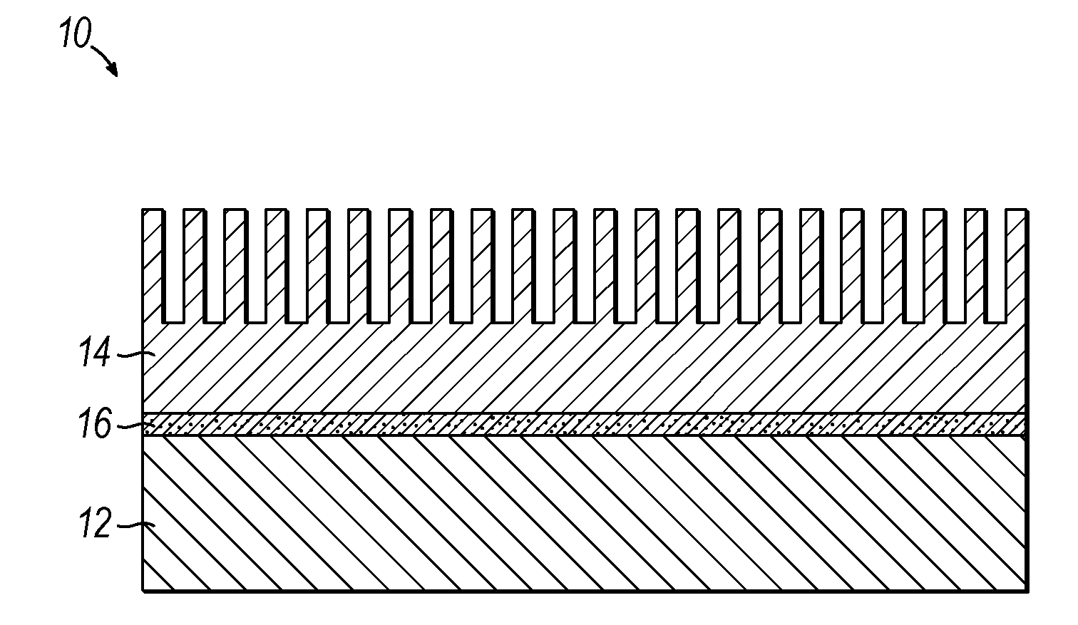
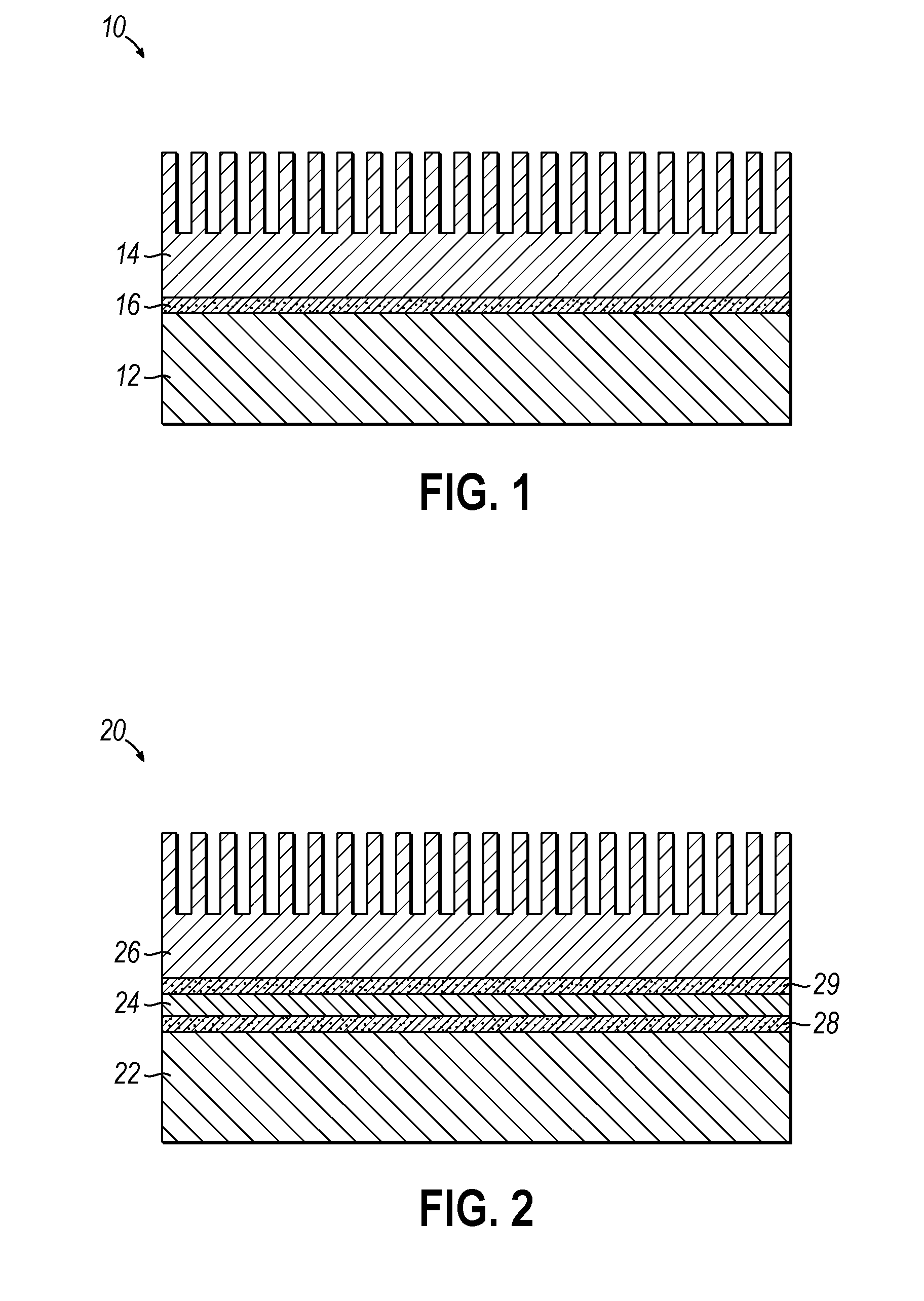
[0016]Embodiments of the present invention relate to an electronic assembly that includes a first element configured to generate heat during operation, a second element configured to transfer away the heat generated by the first element; and a layer of a thermal interface material situated between the first element and the second element. As shown in FIG. 1, an electronic chip module 10 includes an electronic chip 12, a heat sink 14, and a layer of thermal interface material 16 situated between and in intimate contact with both the electronic chip 12 and the heat sink 14. The configuration represented in FIG. 1 is known in the art as TIM 1. With reference to FIG. 2, another configuration for an electronic chip module 20 includes an electronic chip 22, a heat spreader 24, and a heat sink 26. A first layer of thermal interface material 28 is situated between and in intimate contact with both the electronic chip 22 and the heat spreader 24, and a second layer of thermal interface material


PUM


Abstract

The present invention is directed to a reversibly adhesive thermal interface material for electronic components and methods of making and using the same. More particularly, embodiments of the invention provide thermal interface materials that include a thermally-reversible adhesive, and a thermally conductive and electrically non-conductive filler, where the thermal interface material is characterized by a thermal conductivity of 0.2 W/m-K or more and an electrical resistivity of 9×10¹¹ ohm-cm or more.

Description


Claims


Application Information

Patent Timeline
Owner IBM CORP
Why Eureka
Try Eureka