Optical lens for lighting fixture
a technology for optical lenses and lighting fixtures, applied in the direction of instruments, lighting and heating apparatus, semiconductor devices for light sources, etc., can solve the problem that the design of optical lenses on the inner curved surface of art techniques is not disclosed, and achieve the effect of improving light utilization efficiency and uniform illumination
- Summary
- Abstract
- Description
- Claims
- Application Information
AI Technical Summary
Benefits of technology
Problems solved by technology
Method used
Image

Examples
first embodiment
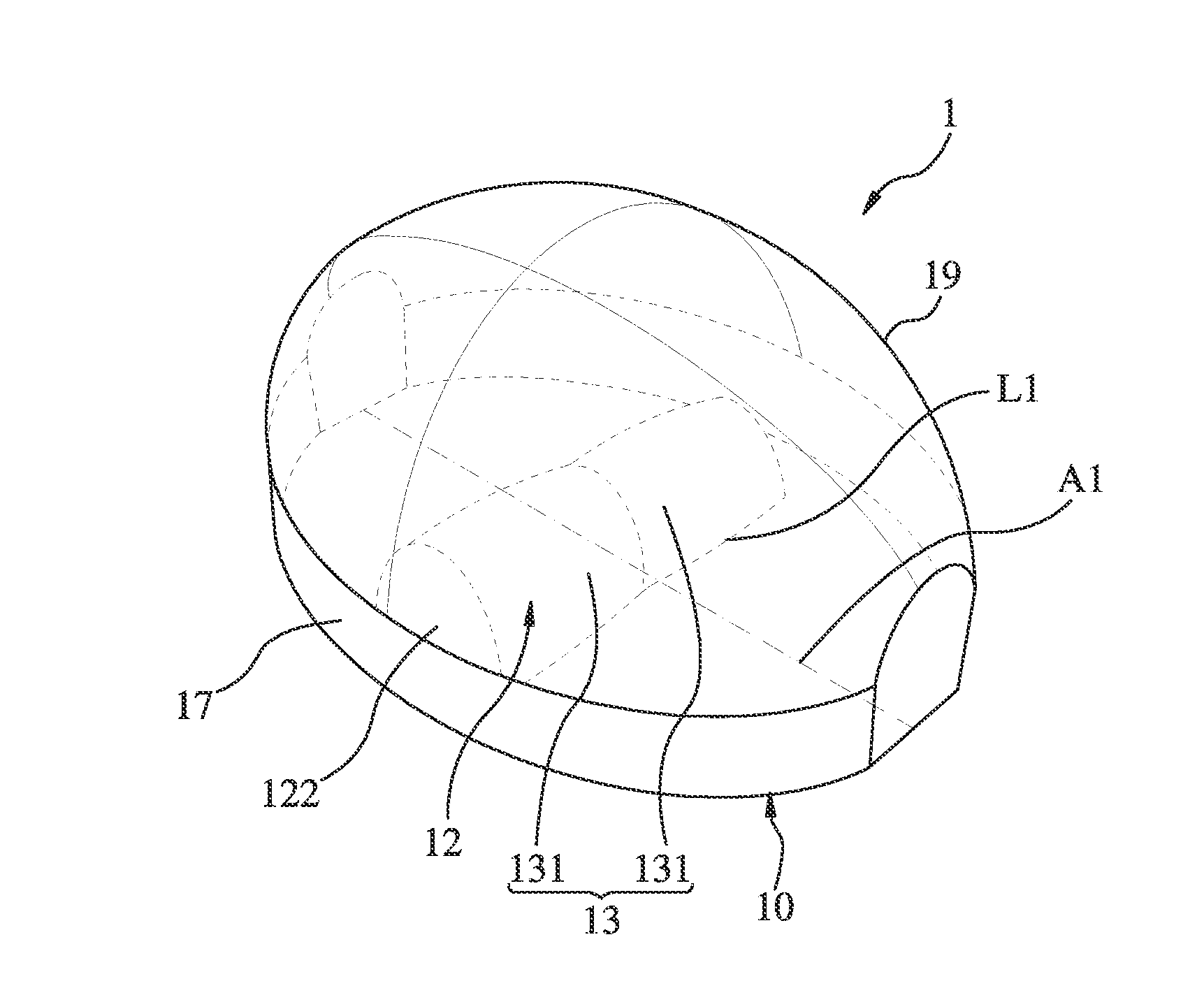
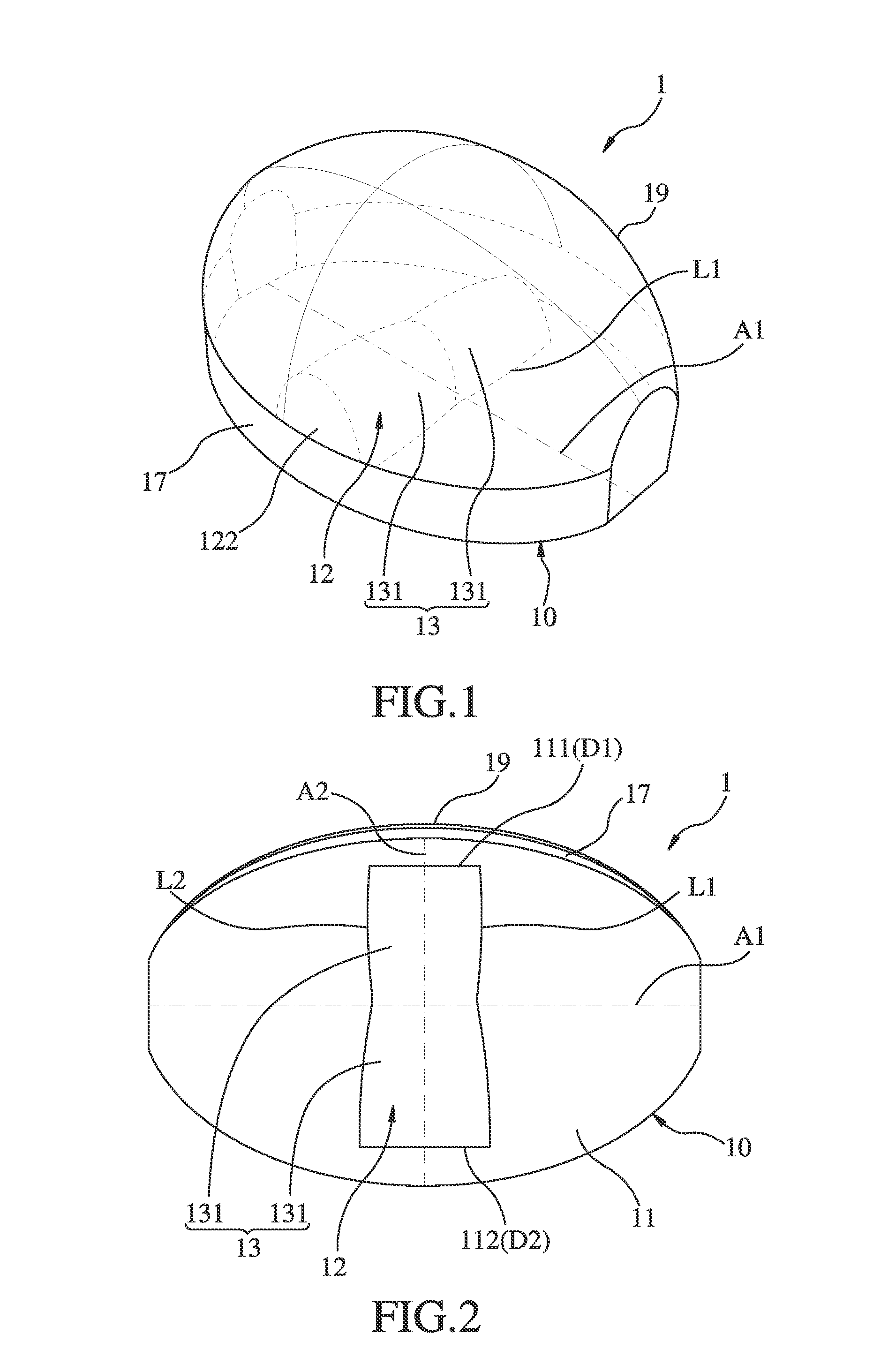
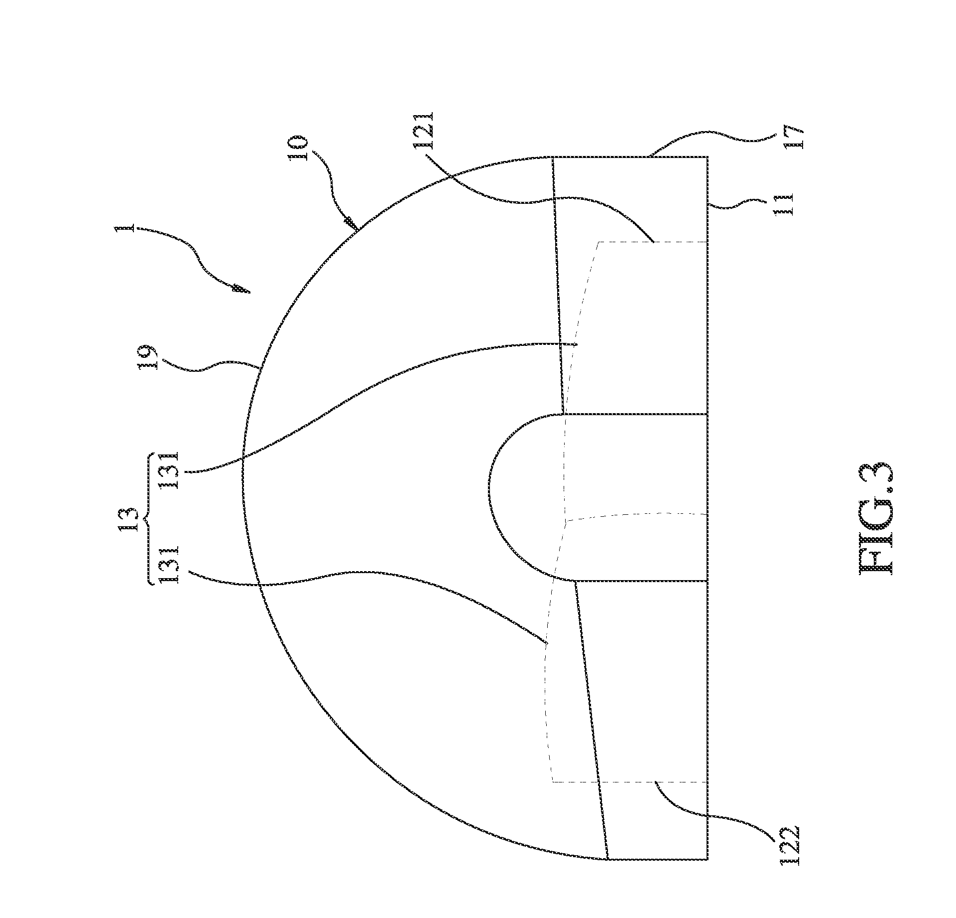
[0039]Referring to FIGS. 1-5, an optical lens for lighting fixture in accordance with the present invention is shown. The optical lens, referenced by 1, comprises a lens body 10.
[0040]The lens body 10 comprises a bottom surface 11 located at a bottom side thereof, a light-exit surface 19 located at a top side thereof, an elongated groove 12 being concave in the direction towards the inner side of the body formed in the bottom surface 11 for accommodating a light source (not shown), and a light incident surface 13 formed of the radial wall of the elongated groove 12 and extending along the length of the elongated groove 12. Further, the bottom surface 11 of the lens body 10 defines a first axis A1 that extends between two opposing ends thereof, and a second axis A2 that extends between two opposing sides thereof across the first axis A1 in a perpendicular manner. The first axis A1 is longer than the second axis A2. In this embodiment, the light source is a LED light source. Further, the
second embodiment
[0058]The maximum SAGi of this second embodiment is 0.075. When put this maximum SAGi of 0.075 into |SAGi / first distance|×100 of the equation (1), the result is 2.5 and is smaller than 2.8, satisfying the equation (1).
[0059]The related data of this second embodiment can be gathered into the following Table II.
TABLE IILuminous fluxof lightingluminous fluxlightminimumaveragefixtureon the roadutilizationilluminanceilluminanceuniformity of(unit: lm)(unit: lm)efficiency(unit: lux)(unit: lux)illuminationEmbodiment 210000742574.3%11.623.20.50
[0060]Thus, the light utilization efficiency of this second embodiment is 74.3% better than the light utilization efficiency of 60% of the prior art design; the uniformity of illumination of this third embodiment is 0.50 better than the uniformity of illumination of 0.4 of the prior art design.
[0061]The other structural features and effect of this second embodiment are similar to the aforesaid first embodiment. No further detailed description in this re
third embodiment
[0064]The maximum SAGi of this third embodiment is 0.0375. When put this maximum SAGi of 0.0375 into |SAGi / first distance|×100 of the equation (1), the result is 1.25 and is smaller than 2.8, satisfying the equation (1).
[0065]The related data of this third embodiment can be gathered into the following Table III.
TABLE IIILuminous fluxof lightingLuminous fluxlightminimumaveragefixtureon the roadutilizationilluminanceilluminanceuniformity of(unit: lm)(unit: lm)efficiency(unit: lux)(unit: lux)illuminationEmbodiment 310000750075.0%12.923.40.55
[0066]Thus, the light utilization efficiency of this third embodiment is 75% better than the light utilization efficiency of 60% of the prior art design; the uniformity of illumination of this third embodiment is 0.55 better than the uniformity of illumination of 0.4 of the prior art design.
[0067]The other structural features and effect of this third embodiment are similar to the aforesaid first embodiment. No further detailed description in this reg
PUM
 Abstract
Description
Claims
Application Information
 - R&D Engineer
- R&D Manager
- IP Professional
- Industry Leading Data Capabilities
- Powerful AI technology
- Patent DNA Extraction
Browse by: Latest US Patents, China's latest patents, Technical Efficacy Thesaurus, Application Domain, Technology Topic.
© 2024 PatSnap. All rights reserved.Legal|Privacy policy|Modern Slavery Act Transparency Statement|Sitemap