Photomask pattern and method for forming the same

Active Publication Date: 2015-07-02
SEMICON MFG INT (SHANGHAI) CORP
View PDF1 Cites 0 Cited by
  • Summary
  • Abstract
  • Description
  • Claims
  • Application Information

AI Technical Summary

Benefits of technology

[0007]One aspect of the present disclosure includes methods for forming a photomask pattern. In an exemplary method, a to-be-etched pattern can be provided. The to-be-etched pattern can be divided into a first mask pattern and an initial second mask pattern. The first mask pattern can include one or more first patte

Problems solved by technology

With continuous shrinking of semiconductor process node dimensions, conventional lithography process, i.e., a patterning process that uses one photomask, has encountered limitation.
That is, because the pitch between adjacent patterns is often too small, adhering between adjacent patterns can occur due to an optical proximity effect.
Typica

Method used


Image

  • Photomask pattern and method for forming the same
  • Photomask pattern and method for forming the same
  • Photomask pattern and method for forming the same

Examples


Embodiment Construction

[0014]Reference will now be made in detail to exemplary embodiments of the disclosure, which are illustrated in the accompanying drawings. Wherever possible, the same reference numbers will be used throughout the drawings to refer to the same or like parts.

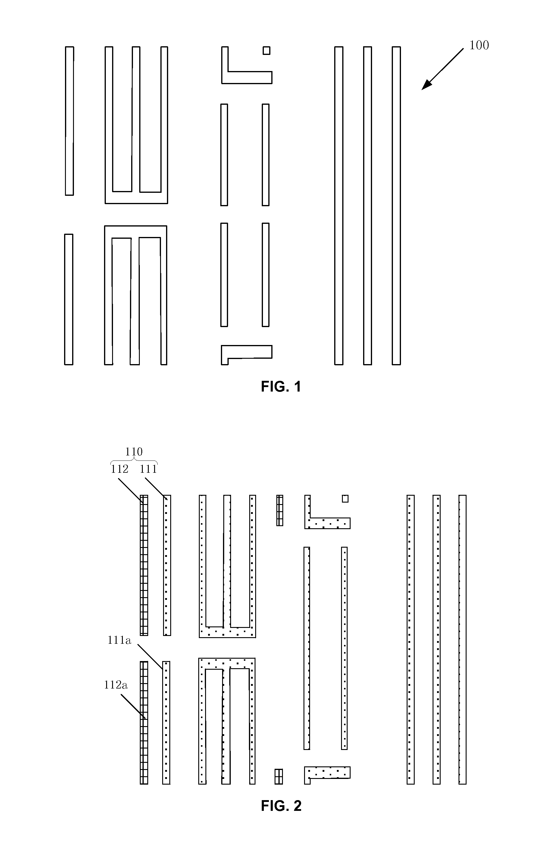
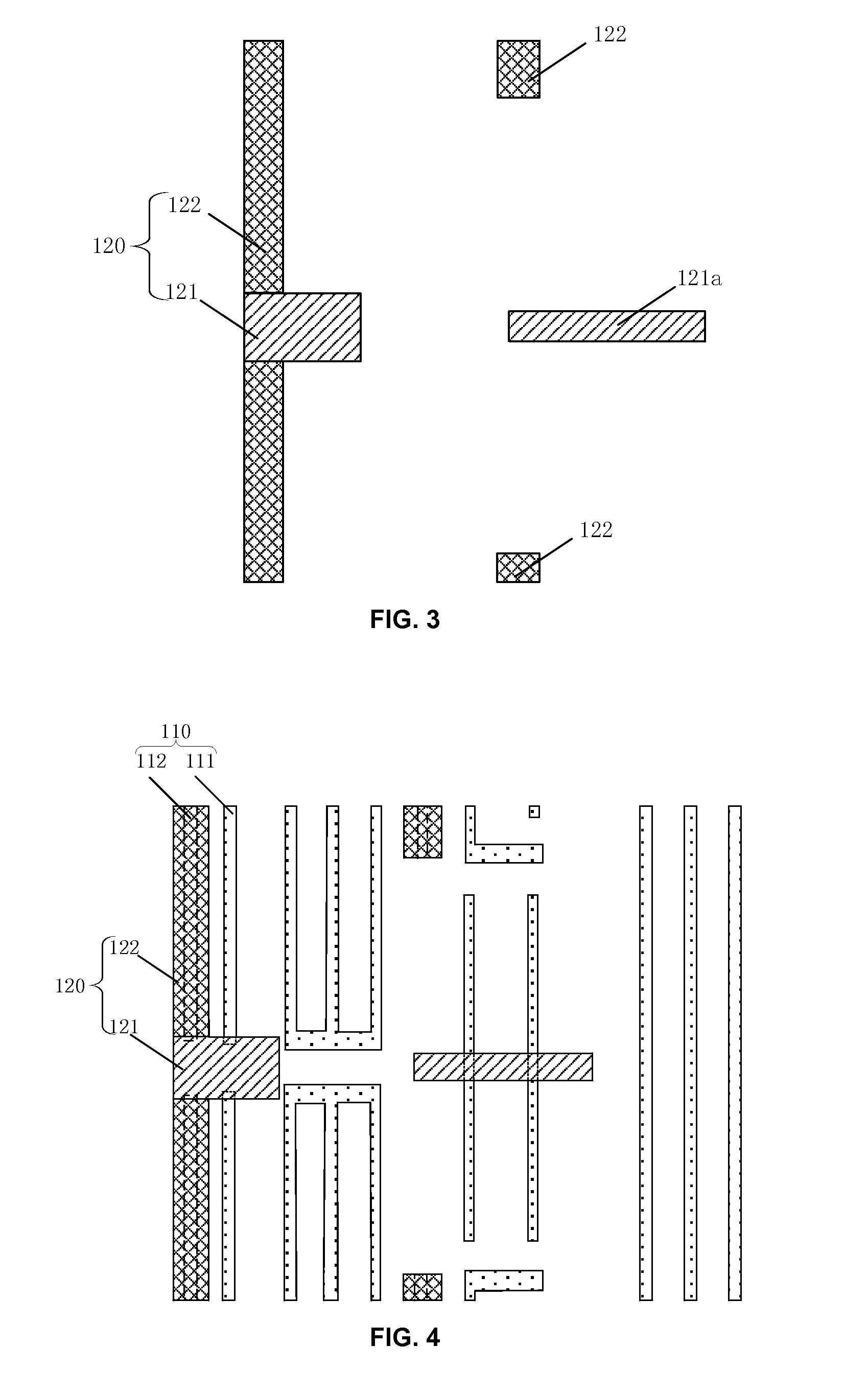
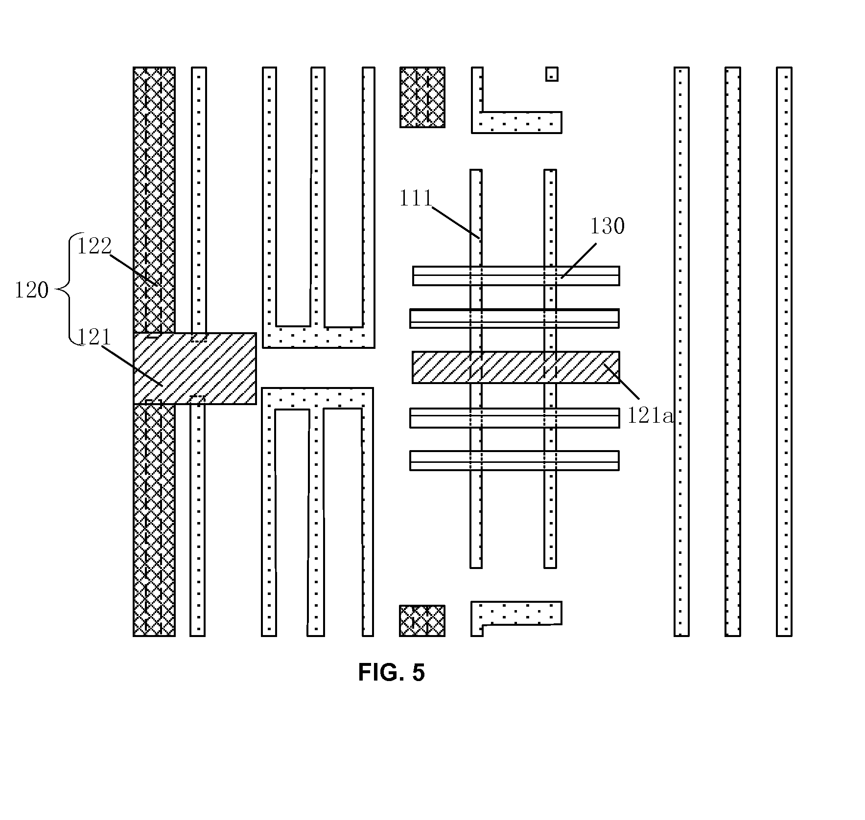
[0015]During a double patterning process, photomask pattern of a second mask layer (i.e., a second mask pattern) has a relatively low pattern density and an uneven distribution of pattern density, which can cause the size of exposed patterns to have poor accuracy during a second patterning process. The pattern density of the second mask pattern can be adjusted by adding a non-print scattering pattern to the second mask pattern. The non-print scattering pattern can be formed such that damage to a pattern previously formed during a first patterning process can be prevented. Further, the size of the non-print scattering pattern can be relatively small and can be lower than the resolution of the photolithography process. Therefore, the n


PUM


Abstract

Various embodiments provide photomask patterns and methods for forming the same. In an exemplary method, a to-be-etched pattern can be provided. The to-be-etched pattern can be divided into a first mask pattern and an initial second mask pattern. The first mask pattern can include one or more first patterns and the initial second mask pattern can include one or more second patterns. A second print scattering pattern can be formed and added to the initial second mask pattern. A position of the second print scattering pattern can be separated from a position of the one or more first patterns of the first mask pattern.

Description


Claims


Application Information

Patent Timeline
Owner SEMICON MFG INT (SHANGHAI) CORP
Why Eureka
Try Eureka