Fluorescence analysis method based on HCR and cation exchange reaction of hydrogel

A cation exchange and fluorescence analysis technology, applied in the field of molecular detection, can solve the problems of cumbersome operation, limit the detection of trace analytes, etc., to improve the reaction efficiency, facilitate the detection of low-abundance substances, and increase the load.

Active Publication Date: 2020-10-02
NANJING UNIV
View PDF15 Cites 1 Cited by
  • Summary
  • Abstract
  • Description
  • Claims
  • Application Information

AI Technical Summary

Benefits of technology

The technical effect of this patented innovative approach described in the current patents relating to combining 3D hydro gel carrier technology (HCG), combinational helix nucleic acids amplifying process(CARPINA) and catheter exchanging fluorescent polymerization technique (CEF). These techniques allow for precise identification of small amounts of targeted microorganisms or other materials like proteins that are difficult to measure accurately due to their size limitations.

Problems solved by technology

This patents describes how to use fluorescein assay techniques to detect specific types of compounds called targets like nucleation sites within gene clusters involved in cellular processes. These techniques involve combining labeled probes together through hybrisynthesis, followed by binding them into larger structures containing quantum dots. By doing this process, they become more effective at amplifying weak light emissions from excited states compared to traditional methods requiring expensive equipment. Additionally, current methods require complicated procedures involving chemical modification and purifications, making them time-consuming and limited in terms of sensibility and applicabilities.

Method used


Image

  • Fluorescence analysis method based on HCR and cation exchange reaction of hydrogel
  • Fluorescence analysis method based on HCR and cation exchange reaction of hydrogel
  • Fluorescence analysis method based on HCR and cation exchange reaction of hydrogel

Examples


Embodiment 1

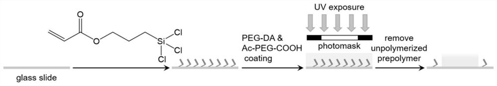
[0036] Embodiment 1: in combination with figure 1 , Silanization of glass sheets and preparation of hydrogel arrays

[0037] (1) Preparation of silanized substrates: Ultrasonic cleaning of ordinary glass sheets with acetone, ethanol and deionized water for 2 minutes respectively, blowing dry with nitrogen gas, and then treating them with a plasma cleaner to activate surface hydroxyl groups, and then putting them into 0.05% (v / v) silylating agent (3-acryloyloxypropyltrichlorosilane) in anhydrous toluene for 1 hour in a nitrogen-filled glove bag. Afterwards, the glass slides were cleaned with toluene, ethanol and deionized water, blown dry with nitrogen gas, and cured in an oven at 100°C for 2 hours, and stored in a dry box for future use.

[0038] (2) Preparation of hydrogel array: first prepare the prepolymer solution, 7.5% (v / v) PEG-DA (MW700), 22.5% (v / v) 20mM PEG-DA aqueous solution (MW 3400), 40% (v / v) PEG (MW 200), 15% (v / v) 20mM Acryl-PEG-COOH in water, and 10%

Embodiment 2

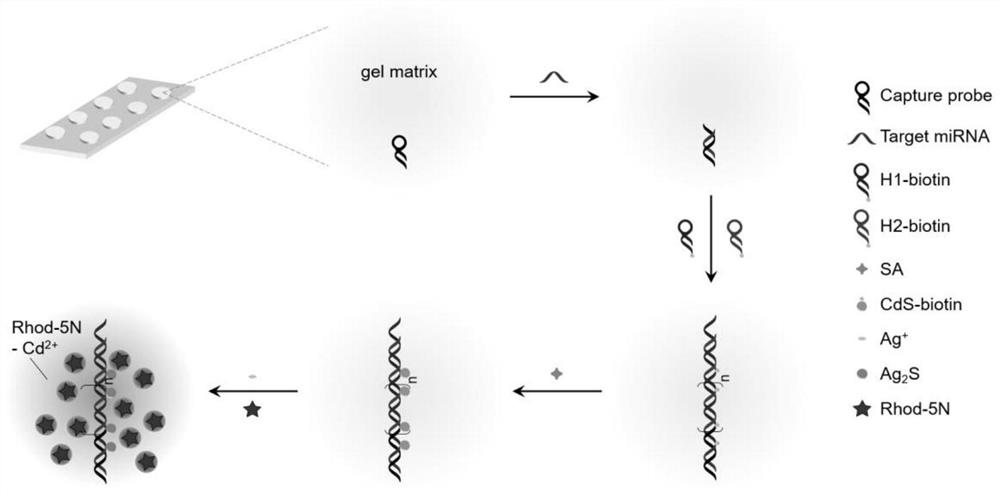
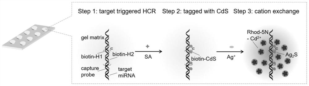
[0039] Embodiment 2: in combination with figure 2 , taking miRNA-21 as an example to illustrate that the fluorescence analysis method based on hydrogel HCR and cation exchange reaction is used for the detection of microRNA

[0040] (1) Probe modification: Activate the carboxyl group of the hydrogel array with 0.4M EDC / 0.1M NHS MES buffer (25mM, pH5.5) at room temperature for 40 minutes, add 10μL of 0.5μM capture solution to each array spot after washing Probe CP, placed in a humid chamber overnight at room temperature.

[0041] (2) Hybridization chain reaction: first, drop 10 μL containing different concentrations of standard miRNA or samples to be tested at each array point, incubate at 37°C for 1 hour, then add 10 μL of an equal volume mixed solution of 1 μM hybridization chain hairpin H1 and H2 dropwise after washing, Incubate at 37°C for 2 hours, the DNA single strand of the capture probe triggers the hybridization chain reaction between H1 and H2, and assembles at the se


PUM


Abstract

The invention relates to a fluorescence analysis method based on HCR and cation exchange reaction of hydrogel, and the method comprises the following steps: modifying a C-C double bond on the surfaceof a substrate through a silanization reaction, and constructing a PEG hydrogel array on the substrate by means of a photomask through a free radical polymerization reaction initiated by ultraviolet light; opening a hairpin structure of a capture probe modified on the hydrogel by the target molecule, initiating a hybridization chain reaction between biotinylation hairpins H1 and H2, and forming along-chain double-chain DNA at a sensing site. Through biotin-streptavidin specific binding reaction, a biotinylated quantum dot CdS is fixed to a sensing site. CdS is initiated by Ag<+> to generate cation exchange reaction, and the fluorescence of Rhod-5N is greatly enhanced by Cd2<+>. Array point fluorescence is quantified by using a gene chip scanner, so that high-sensitivity and high-specificity analysis of target molecules is realized. The method is simple to operate, low in cost, high in sensitivity, good in specificity and high in universality.

Description


Claims


Application Information

Patent Timeline
Owner NANJING UNIV
Why Eureka
Try Eureka