Liquid jet head and liquid jet apparatus
- Summary
- Abstract
- Description
- Claims
- Application Information
AI Technical Summary
Benefits of technology
Problems solved by technology
Method used
Image

Examples
first embodiment
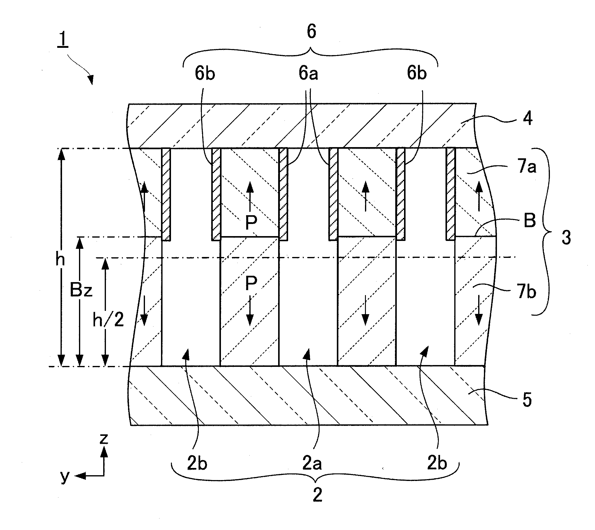
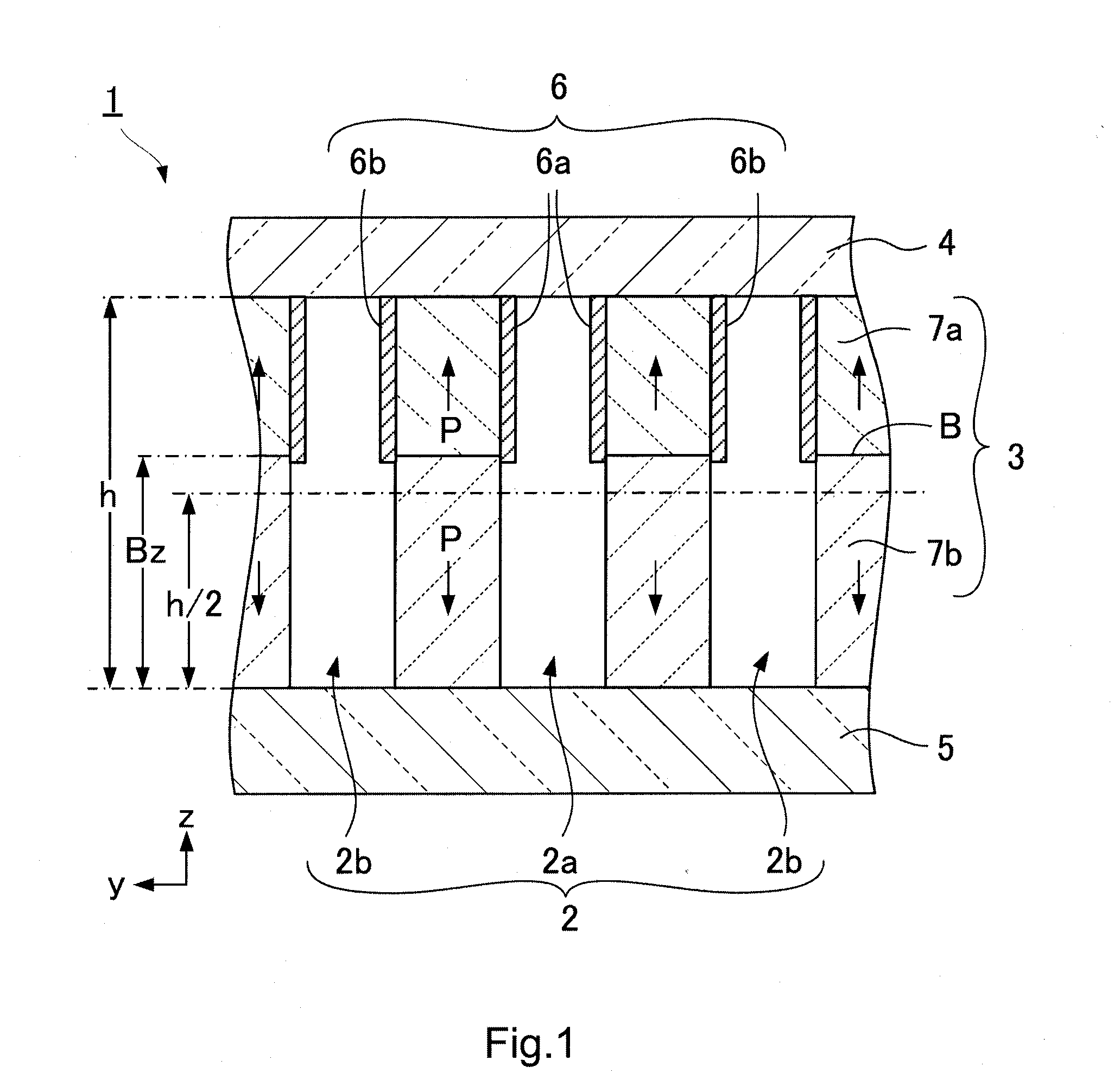
[0026]FIG. 1 is a schematic cross-sectional view of channels applied to a liquid jet head 1 according to a first embodiment of the present invention. The first embodiment represents a basic configuration of the present invention. As illustrated in FIG. 1, the liquid jet head 1 includes a channel 2, a side wall 3 made of a piezoelectric material and arranged between the channels 2, an upper member 4 fixed to an upper end of the side wall 3 and installed on an upper portion of the channel 2, a lower member 5 fixed to a lower end of the side wall 3 and installed on a lower portion of the channel 2, and an electrode 6 installed on a wall surface of the side wall 3. The side wall 3 has two piezoelectric materials having mutually different polarization directions and laminated in a height direction (z direction), interposing a polarization boundary B. A height Bz of the polarization boundary B is positioned above h / 2 of a height h of the side wall 3. The electrode 6 is installed from an up
second embodiment
[0036]FIGS. 3A and 3B are explanatory diagrams of a liquid jet head 1 according to a second embodiment of the present invention. FIG. 3A is a schematic exploded perspective view of the liquid jet head 1, and FIG. 3B is a schematic cross-sectional view of an ejection channel 2a along a longitudinal direction (x direction). The liquid jet head 1 is an edge shoot-type liquid jet head. The same portions or portions having the same function are denoted with the same reference sign.
[0037]As illustrated in FIGS. 3A and 3B, the liquid jet head 1 includes a piezoelectric body substrate 7, a cover plate 9 installed on an upper surface UP of the piezoelectric body substrate 7, and a nozzle plate 8 installed at an end surface of one side of the piezoelectric body substrate 7. The ejection channel 2a and a non-ejection channel 2b, which are narrow and long in an x direction, are alternately formed in a y direction in the piezoelectric body substrate 7. A side wall 3 is installed between the ejectio
third embodiment
[0043]FIGS. 4A and 4B are explanatory diagrams of a liquid jet head 1 according to a third embodiment of the present invention. FIG. 4A is a schematic exploded perspective view of the liquid jet head 1, and FIG. 4B is a schematic cross-sectional view of an ejection channel 2a along a longitudinal direction (x direction). The liquid jet head 1 is a side shoot-type liquid jet head. The same portions or portions having the same function are denoted with the same reference sign.
[0044]As illustrated in FIGS. 4A and 4B, the liquid jet head 1 includes a piezoelectric body substrate 7, a nozzle plate 8 installed on an upper surface UP of the piezoelectric body substrate 7, and a cover plate 9 installed on a lower surface LP of the piezoelectric body substrate 7. The ejection channel 2a and a non-ejection channel 2b, which are long and narrow in the x direction, are alternately formed in a y direction in the piezoelectric body substrate 7. A side wall 3 is installed between the ejection channel
PUM
 Abstract
Description
Claims
Application Information
 - R&D Engineer
- R&D Manager
- IP Professional
- Industry Leading Data Capabilities
- Powerful AI technology
- Patent DNA Extraction
Browse by: Latest US Patents, China's latest patents, Technical Efficacy Thesaurus, Application Domain, Technology Topic.
© 2024 PatSnap. All rights reserved.Legal|Privacy policy|Modern Slavery Act Transparency Statement|Sitemap