System for measuring displacement of accelerating tube in high-vacuum chamber by using micro-alignment telescope and method thereof

Active Publication Date: 2017-06-15
INST FOR BASIC SCI
View PDF0 Cites 2 Cited by
  • Summary
  • Abstract
  • Description
  • Claims
  • Application Information

AI Technical Summary

Benefits of technology

[0012]An object of the present invention is to provide a system and a method for measuring displacement of an accelerating tube in a high-vacuum chamber, which is capable of precisely measuring and correcting a position

Problems solved by technology

However, since a chamber is deformed due to vacuum, the reliability of a measured value from these methods cannot be high.
In addition, when the inner temperature of a chamber is high or har

Method used


Image

  • System for measuring displacement of accelerating tube in high-vacuum chamber by using micro-alignment telescope and method thereof
  • System for measuring displacement of accelerating tube in high-vacuum chamber by using micro-alignment telescope and method thereof
  • System for measuring displacement of accelerating tube in high-vacuum chamber by using micro-alignment telescope and method thereof

Examples


Embodiment Construction

[0026]The terminology and words used herein and accompanying claims should be not interpreted as the meanings of commonly used dictionaries, but interpreted as having meanings according to the technical sprit of the present invention on the principle that the concepts of the terminology and the words can be defined by the inventor in order to explain the present invention in the best mode.

[0027]Throughout the whole specification, when a predetermined part “includes” a predetermined component, the predetermined part does not exclude other components, but may further include other components unless the context clearly indicates otherwise. In addition, the terms “part”, “machine”, “module”, “device”, or “step” refer to units to process at least one function or operation, and is realized. by hardware or software, or the combination of the hardware and the software.

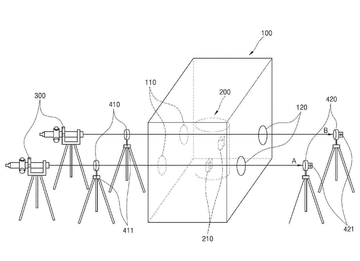
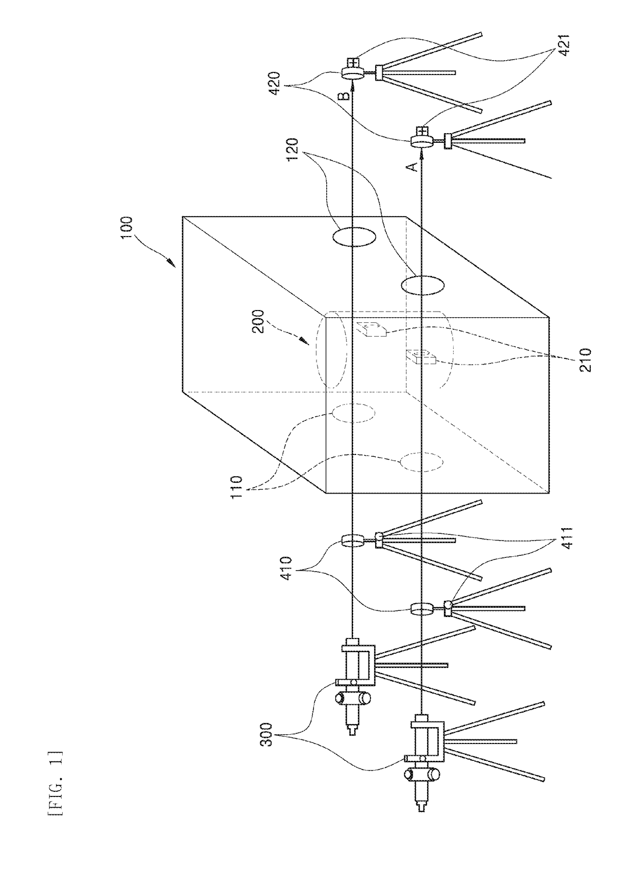
[0028]Hereinafter, a system for measuring displacement of an accelerating tube in a high-vacuum chamber by using a micro-alignm


PUM


Abstract

A system for measuring displacement of an accelerating tube by using a micro-alignment telescope, which includes a vacuum chamber; a hollow accelerating tube in the vacuum chamber; a sighting target attached to a surface of the accelerating tube while protruding from the surface of the accelerating tube; the micro-alignment telescope spaced apart from one side surface of the vacuum chamber; a first lens device interposed between the micro-alignment telescope and the vacuum chamber; and a second lens device spaced apart from an opposite side surface of the vacuum chamber by a distance, wherein the vacuum chamber includes first and second viewports placed on the surfaces of the vacuum chamber in correspondence with each other, and the micro-alignment telescope, the first lens device, the first viewport, the sighting target, the second viewport and the second lens device are aligned on a same axis in one direction.

Description


Claims


Application Information

Patent Timeline
Owner INST FOR BASIC SCI
Why Eureka
Try Eureka