Power supply device and electric vehicle provided with power supply device

a technology of power supply device and power supply device, which is applied in the direction of vehicle sub-unit features, cell components, batteries, etc., to achieve the effect of preventing lateral displacement of battery cells, preventing rotation of bent pieces, and preventing displacement of bind bars

Pending Publication Date: 2021-01-14
SANYO ELECTRIC CO LTD
View PDF8 Cites 0 Cited by
  • Summary
  • Abstract
  • Description
  • Claims
  • Application Information

AI Technical Summary

Benefits of technology

The technical effect of this patented technology is its ability to securely hold two parts together without rotating them when they shouldn't be moved or adjusted during assembly process. This makes it easier for components to have their own position on top due to less space needed compared to traditional methods like screws.

Problems solved by technology

This patented technical problem addressed in this patents relating to conventional batteries used for electricity storage devices involves maintaining tight contact between each individual cell within an electrode assembly during use without causing damage or deformation over time due to external factors such as vibrations caused by transportation equipment.

Method used


Image

  • Power supply device and electric vehicle provided with power supply device
  • Power supply device and electric vehicle provided with power supply device
  • Power supply device and electric vehicle provided with power supply device

Examples


Embodiment Construction

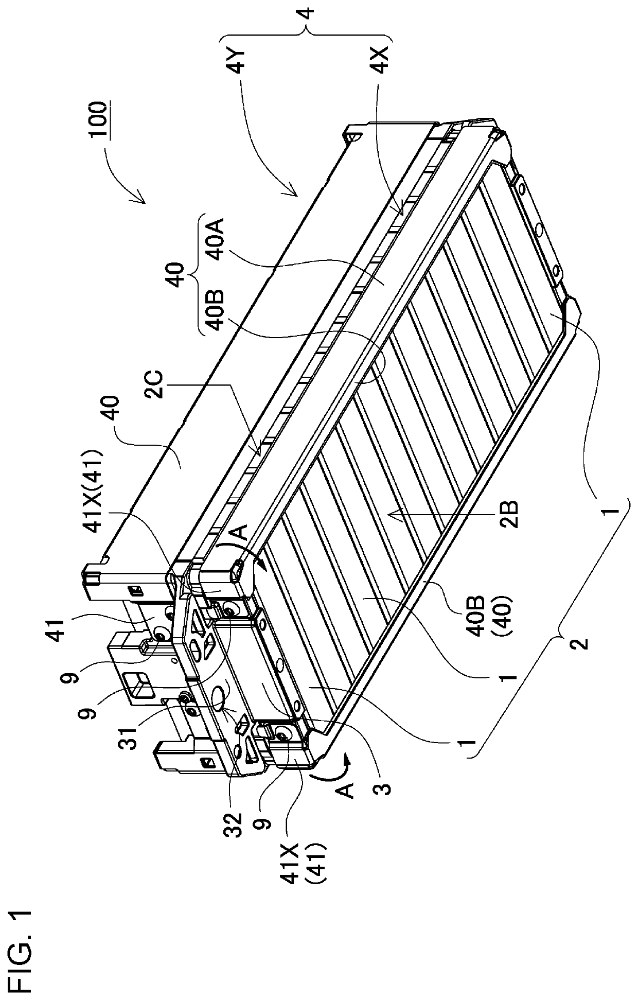
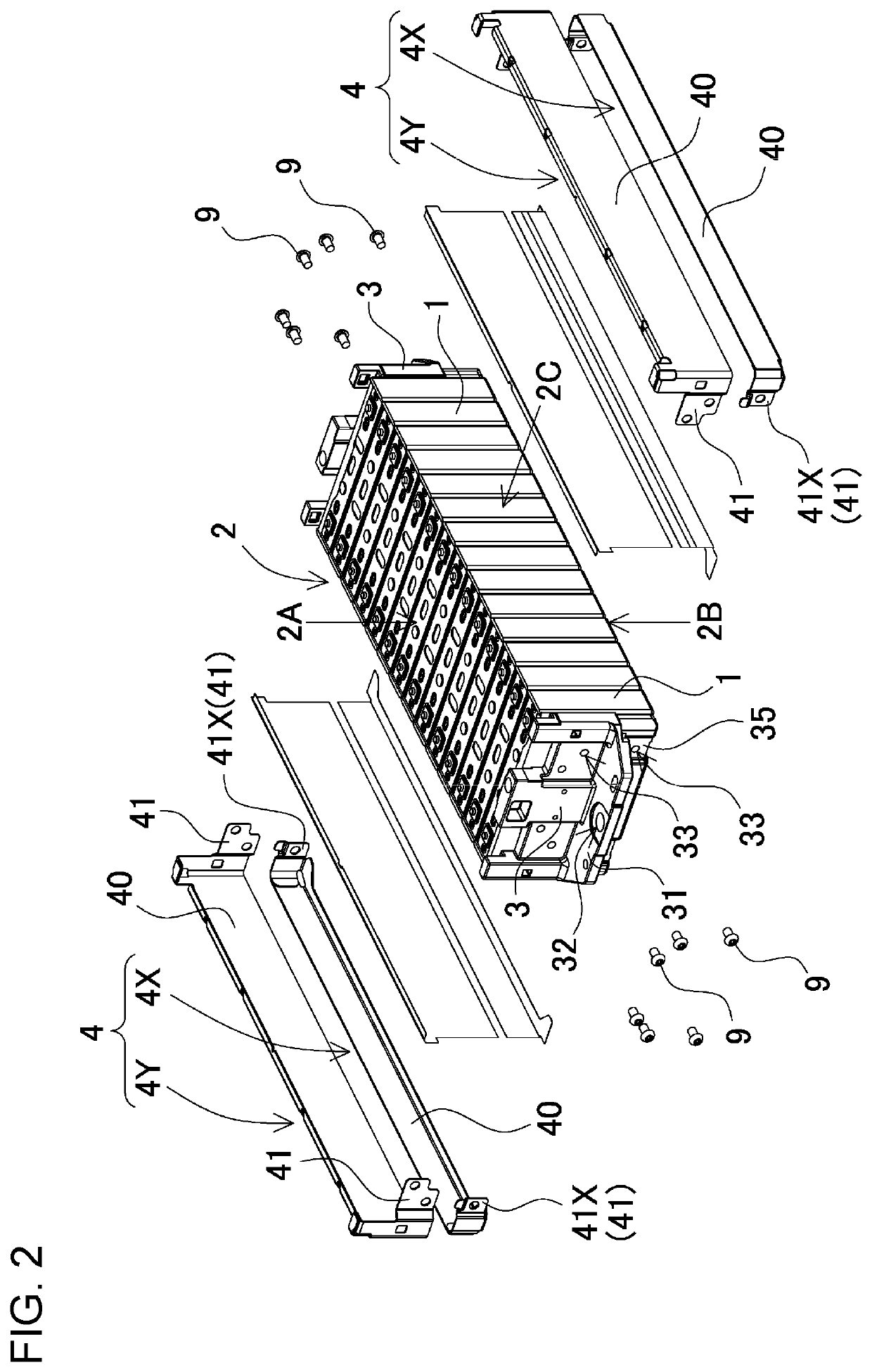
[0016]First, one point of interest of the present invention will be described. A power supply device in which a plurality of battery cells are stacked to form a battery stack and a pair of end plates disposed on both end surfaces of the battery stack are coupled by a bind bar can be made wider in a vertical width to increase a tensile strength. However, since the power supply device is required to have an optimal structure for an application, the bind bar disposed on one surface of the battery stack cannot always be formed of one metal plate, and the bind bar may be required to be vertically divided. For example, in a structure in which a fixing flange for fixing the power supply device to an external device projects in a middle in a vertical direction of the end plates, or in a structure in which there is a projecting portion in a central part of a side surface of the battery stack, the bind bar is required to be vertically divided and to be fixed the end plates. In the power supply d


PUM


Abstract

A power supply device has a structure in which a bind bar having bent pieces at both ends coupled to end plates disposed at both end portions of a battery stack is divided in a width direction of a side surface of the battery stack, the bent piece of each bind bar is bolted to an outer surface of one of the end plates, the one of the end plates is provided with a stopper wall that prevents rotation of a bent piece fixed with a single bolt, which is fixed to the one of the end plates via one bolt, and the bent piece is fitted to a stopper wall to prevent the displacement of the bind bar.

Description


Claims


Application Information

Patent Timeline
Owner SANYO ELECTRIC CO LTD
Why Eureka
Try Eureka