Bonding apparatus

a technology of bonding apparatus and bonding surface, which is applied in the direction of soldering apparatus, auxillary welding devices, manufacturing tools, etc., can solve the problems of large inertia and special difficulty in bonding small balls, and achieve the effect of large bonding area

Inactive Publication Date: 2005-03-08
SHINKAWA CO LTD
View PDF8 Cites 10 Cited by
  • Summary
  • Abstract
  • Description
  • Claims
  • Application Information

AI Technical Summary

Benefits of technology

The technical effect of this patented device is to create an improved way for bonding materials together without having to be moved horizontally or vertically. This means that there can be more material being joined than previously possible due to its larger contact area.

Problems solved by technology

The technical problem addressed by this patent is how to efficiently bond small balls onto a workpiece without requiring excessive space between them and without having to adjust the orientation of the support points during the process.

Method used


Image

  • Bonding apparatus
  • Bonding apparatus
  • Bonding apparatus

Examples


Embodiment Construction

Embodiments of the bonding apparatus of the present invention will be described below with reference to the accompanying drawings.

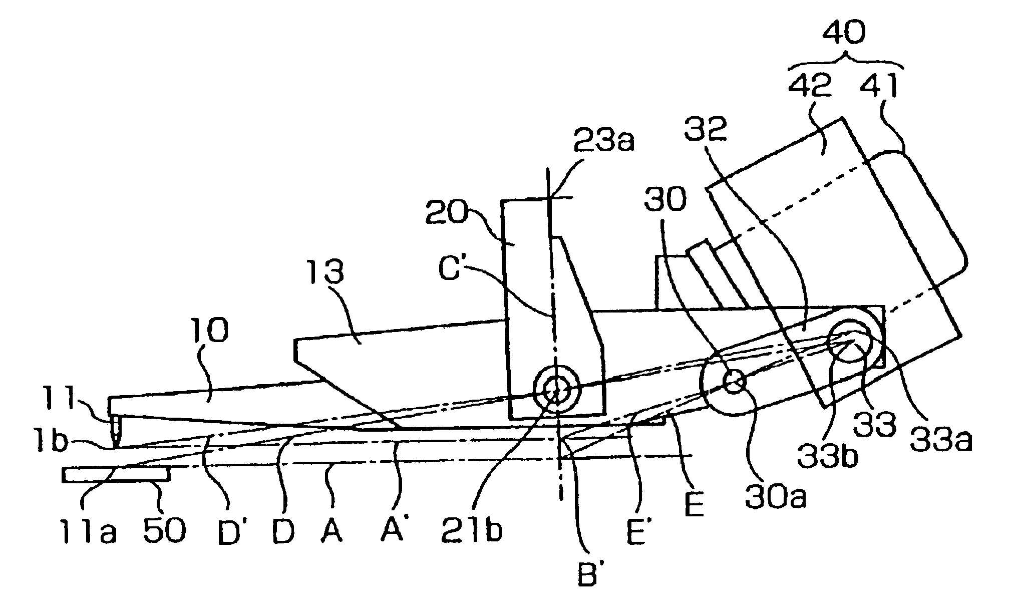
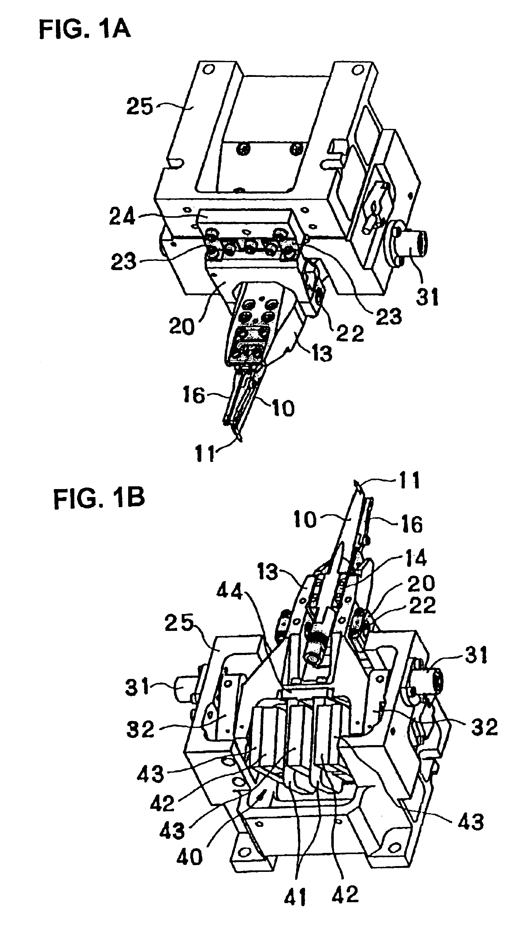
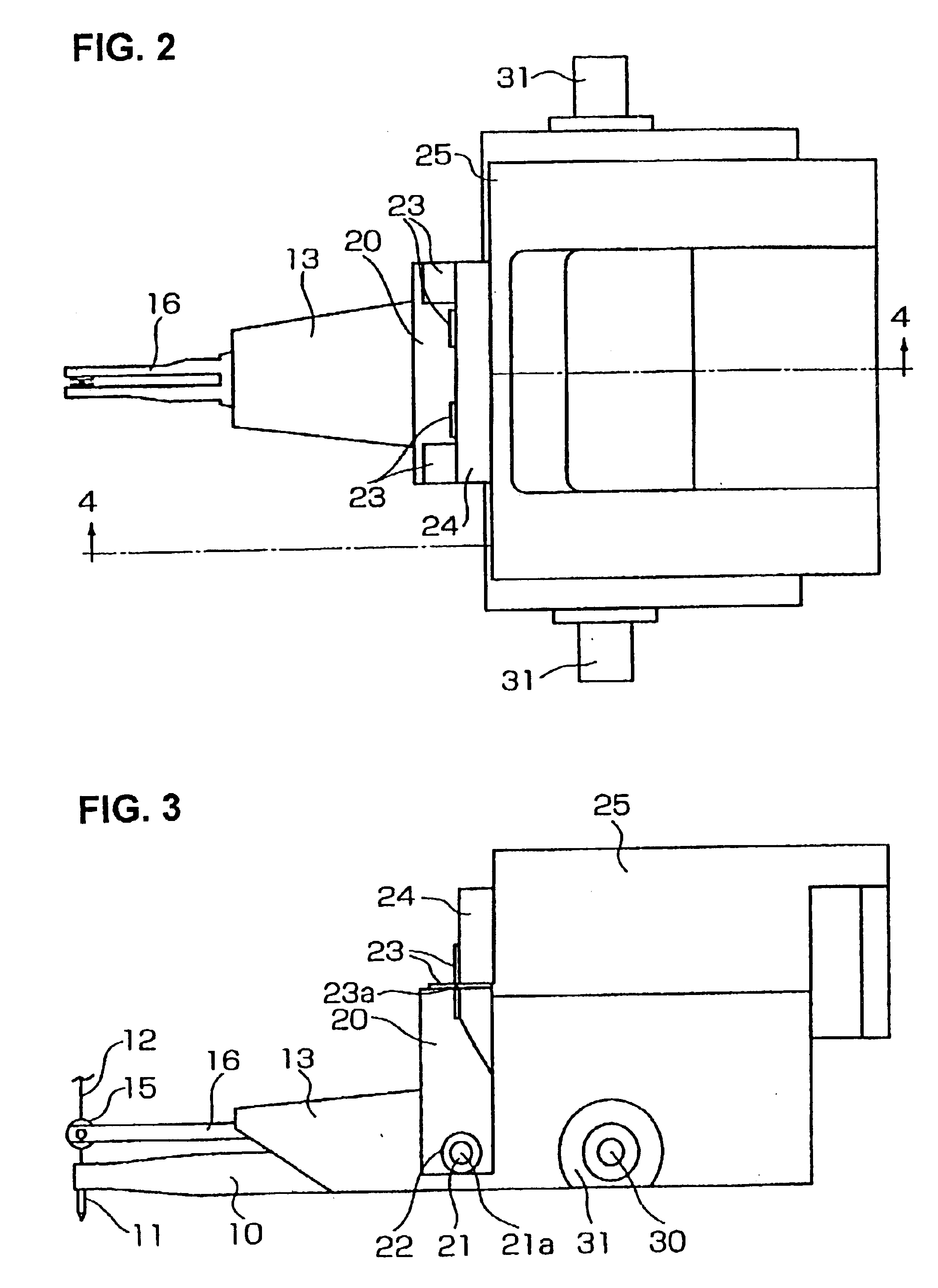
As shown in FIG. 1 and FIGS. 3 through 5, a capillary 11 is fastened to the tip end portion of an ultrasonic horn 10, and a wire 12 which is wound on a wire spool (not shown) passes through the capillary 11. The ultrasonic horn 10 is disposed in a recess formed in the undersurface of a horn holder 13 and is fastened to the horn holder 13 via a connecting plate 14 which has a node part 14a that constitutes a node of vibration of the ultrasonic horn 10. Furthermore, a clamping arm 16 which has a wire damper 15 that holds the wire 12 is disposed above the ultrasonic horn 10, and this clamping arm 16 is fastened to the horn holder 13.

The horn holder 13 is disposed inside the bifurcate shape of a swing arm 20 which is open at the bottom, and horn holder supporting shafts 21 which are fastened to both side surfaces of the horn holder 13 are supported on the swing


PUM

PropertyMeasurementUnit
Heightaaaaaaaaaa

Abstract

A bonding apparatus including an ultrasonic horn having a capillary, a horn holder holding the ultrasonic horn, a swing arm rotatably supporting the horn holder on horn holder supporting shafts, and auxiliary arms which are rotatably supported by auxiliary arm supporting shafts and rotatably supported by connecting shafts on the horn holder. The horn holder supporting shafts are disposed above a hypothetical center of an imaginary horizontal line extending from the tip end of the capillary, the auxiliary arm supporting shafts are disposed in the back of the horn holder supporting shafts and at the same height as the horn holder supporting shafts, and the connecting shafts are disposed at an intersection of an extension of an imaginary line connecting the tip end of the capillary and the horn holder supporting shafts and an extension of an imaginary line connecting the hypothetical center and the auxiliary arm supporting shafts.

Description


Claims


Application Information

Patent Timeline
Owner SHINKAWA CO LTD
Why Eureka
Try Eureka