Zero mark formation method applicable to EPI (epitaxy) process

A technology of zero mark and process, which is applied in the field of zero mark formation suitable for epitaxial EPI process, can solve the problems of step height reduction, product reliability reduction, use, etc., and achieve the effect of enhancing step difference and improving optical contrast

Active Publication Date: 2013-03-06
SHANGHAI HUAHONG GRACE SEMICON MFG CORP
View PDF3 Cites 0 Cited by
  • Summary
  • Abstract
  • Description
  • Claims
  • Application Information

AI Technical Summary

Benefits of technology

This technology improves how well it shows things up on different angles by adjusting certain parameters or features during manufacturing processes. By adding an extra element called a barrier layer between two layers, this process helps improve visibility when looking at them from one side while still maintaining their original appearance.

Problems solved by technology

This patented technical problem addressed in the patents relates to improving the accuracy and conformation of an alignment system during manufacturing of electronic devices such as complementary Metal Oxide Semi-controlled Laterally Diffused Insulators/Furthermore, the challenge presented involves controlling the depth at which certain materials are removed without damaging them while also ensuring stable results when performing different types of processing steps like deposition into shallow holes or deposited onto specific surfaces.

Method used


Image

  • Zero mark formation method applicable to EPI (epitaxy) process
  • Zero mark formation method applicable to EPI (epitaxy) process
  • Zero mark formation method applicable to EPI (epitaxy) process

Examples


Embodiment Construction

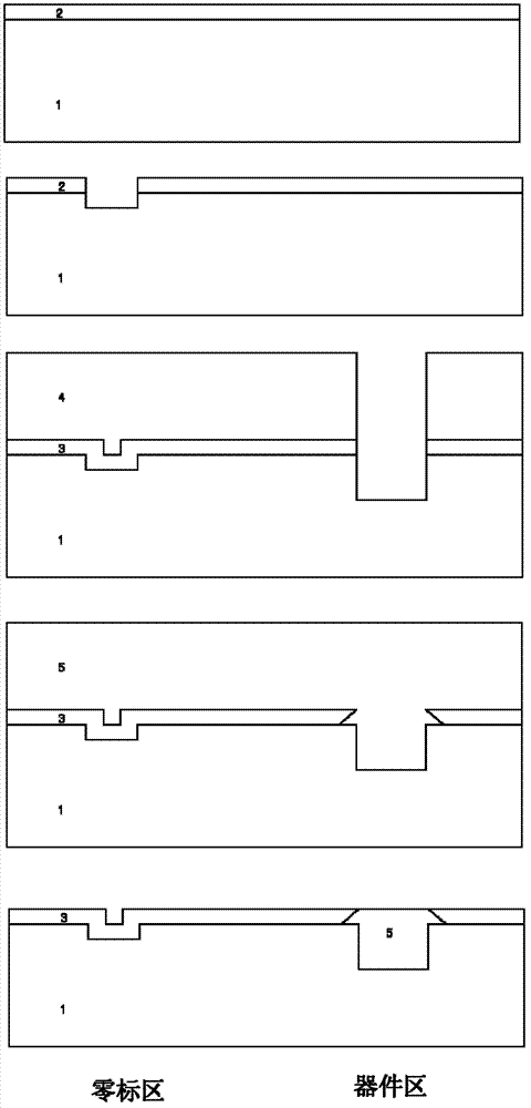
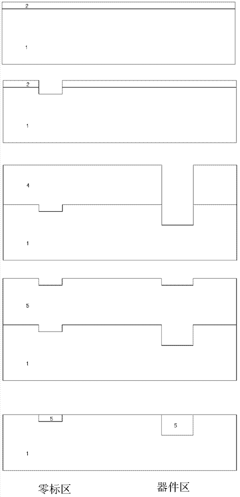
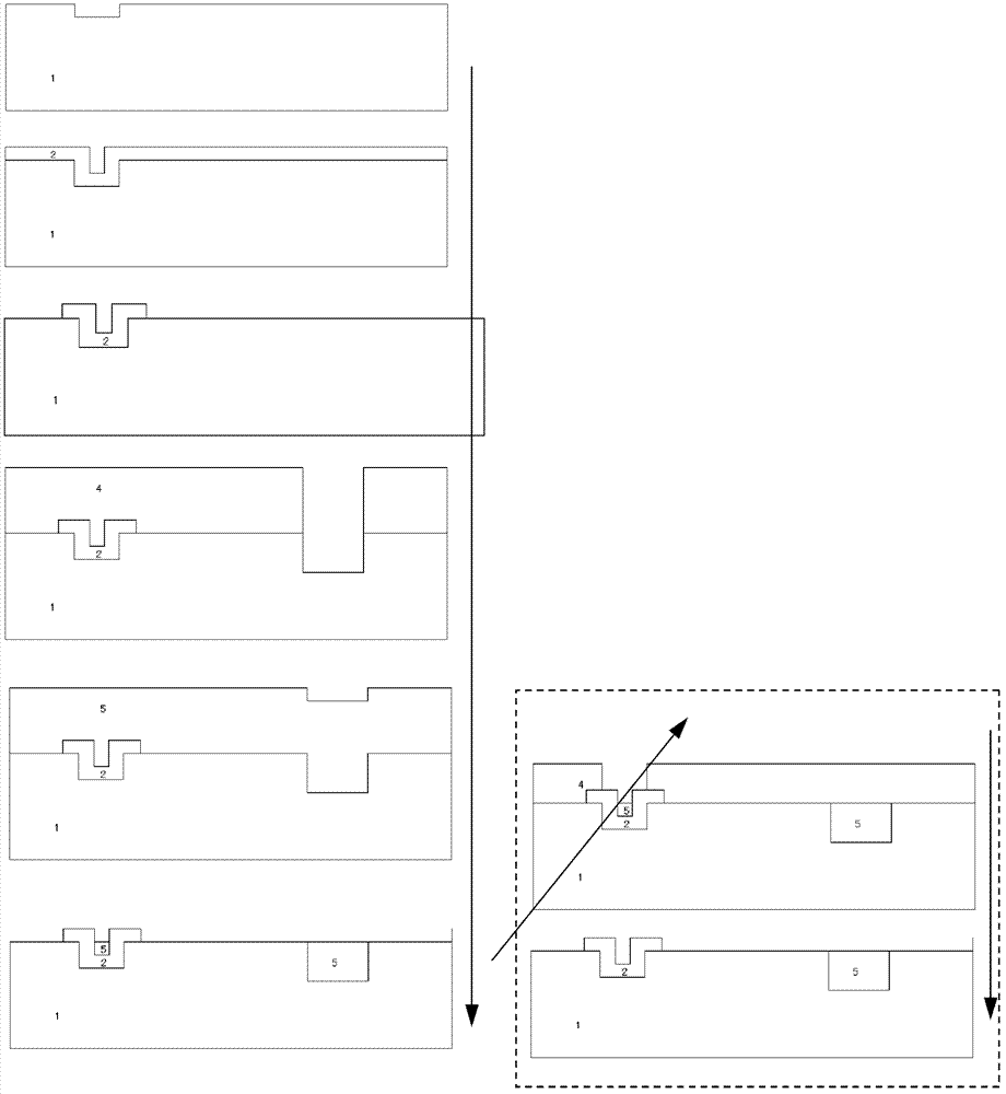
[0024] The invention describes a zero mark forming method suitable for a deep groove etching process without a dielectric barrier layer and a low chemical mechanical grinding CMP polishing amount. Due to the cancellation of the dielectric barrier layer, the zero mark has no epitaxial EPI barrier layer at this time, so the zero mark and the epitaxial EPI grow into one, and the steps are eliminated in the subsequent chemical mechanical polishing CMP, making it unusable. Therefore, it is necessary to use other processes to generate the barrier layer before the epitaxial EPI growth.

[0025] In this process, by changing the process sequence of generating the zero mark, the zero mark is protected by the pad oxide layer, and the pad oxide layer is used as a barrier layer to separate the epitaxial EPI from the zero mark. Enhance the step difference of the zero mark and improve the optical contrast.

[0026] like figure 2 Shown, the present invention comprises the following steps:


PUM


Abstract

The invention discloses a zero mark formation method applicable to EPI (epitaxy) process. The method includes the steps of spin-coating photoresist, exposing a zero layer, etching to form a zero mark with a silicone substrate step, and depositing a lining oxide layer. By the zero mark formation method applicable to EPI process, step difference of the zero mark can be enhanced, and optical contrast can be increased.

Description


Claims


Application Information

Patent Timeline
Owner SHANGHAI HUAHONG GRACE SEMICON MFG CORP
Why Eureka
Try Eureka