Wafer array cathode

A cathode and array technology, applied in the field of microwave sources, can solve problems such as inability to plant, immature flocking technology, poor high temperature ablation resistance, etc., to prolong working life, improve high temperature ablation resistance, and ensure technical performance Effect

Active Publication Date: 2015-12-02
NAT UNIV OF DEFENSE TECH
View PDF5 Cites 3 Cited by
  • Summary
  • Abstract
  • Description
  • Claims
  • Application Information

AI Technical Summary

Problems solved by technology

[0005] The advantage of chemical fiber velvet cathode is that the fluff has good uniformity, so the emission current is uniform, and the disadvantage is that the high temperature ablation resistance is poor, while the high temperature ablation re

Method used


Image

  • Wafer array cathode
  • Wafer array cathode
  • Wafer array cathode

Examples


Embodiment Construction

[0016] The specific embodiments of the present invention will be further described below in conjunction with the accompanying drawings.

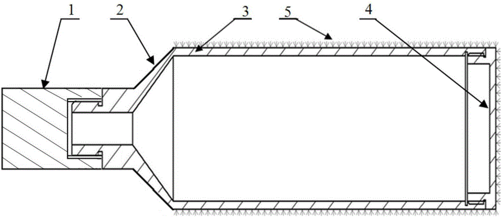
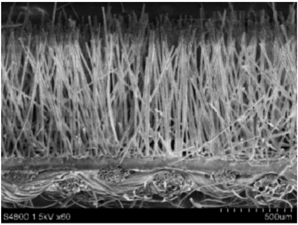
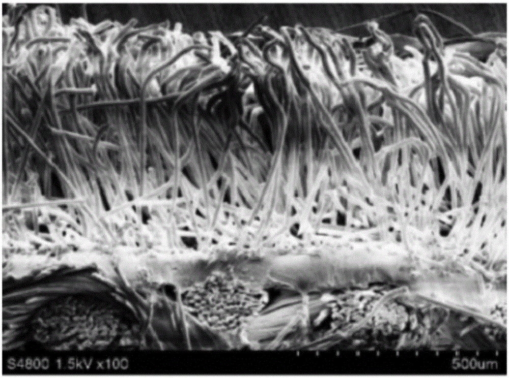
[0017] Figure 4 It is a cross-sectional view of the wafer array cathode of the present invention along the central axis, and the cathode is symmetrical around the axis. The wafer array cathode of the present invention is composed of a cathode seat 1, a tapered section 2, a cathode base 3, a stainless steel ring sheet 4, a dielectric ring sheet 5, and a cathode cap 6. The medium ring sheet 5 is made of carbon fiber cloth or glass fiber cloth, or other materials with low emission threshold and high temperature ablation resistance, and the other parts are made of stainless steel materials.

[0018] The relationship between its structure and assembly is as follows:

[0019] For the convenience of description, it is stipulated below that the end where the cathode holder 1 is located is the left end, and the end where the cathode cap 6 is located is the


PUM


Abstract

The invention relates to a wafer array cathode in the field of high-power microwaves. The wafer array cathode aims to solve the problems of the poor high-temperature ablation resistance property, the short operation life and the like of an existing chemical fiber velvet cathode. According to the technical scheme, stainless steel circular ring slices and medium circular ring slices alternatively sleeve a cathode substrate, the medium circular ring slices are made of carbon fiber cloth or glass fiber cloth which has the good high-temperature ablation resistance property, and cellosilk beams are divergent due to an electrostatic interaction and emit uniform electron beams while in use. The wafer array cathode is advantageous in that the wafer array cathode is simple in structure and easy to implement, the advantage of the good high-temperature ablation resistance property is obtained, the advantage of good emission uniformity is also obtained by utilizing a wafer array structure, and the life of the cathode is improved so that the service life of an MILO is improved.

Description


Claims


Application Information

Patent Timeline
Owner NAT UNIV OF DEFENSE TECH
Why Eureka
Try Eureka