Optical module and laser wavelength shift adjusting method and device of optical module

A wavelength shifting and adjusting method technology, applied in the field of optical communication, can solve the problems of lost data sources, low optical power, etc.

Active Publication Date: 2016-04-20
HISENSE BROADBAND MULTIMEDIA TECH
View PDF5 Cites 9 Cited by
  • Summary
  • Abstract
  • Description
  • Claims
  • Application Information

AI Technical Summary

Problems solved by technology

When the wavelength offset of the light is less than the channel width, this results in a smaller optical power received by the receiving optical device (ROSA); when the wavelength

Method used


Image

  • Optical module and laser wavelength shift adjusting method and device of optical module
  • Optical module and laser wavelength shift adjusting method and device of optical module
  • Optical module and laser wavelength shift adjusting method and device of optical module

Examples


Embodiment Construction

[0046] In order to make the purpose, technical solutions and advantages of the embodiments of the present invention clearer, the technical solutions in the embodiments of the present invention will be clearly and completely described below in conjunction with the drawings in the embodiments of the present invention. Obviously, the described embodiments It is a part of embodiments of the present invention, but not all embodiments. Based on the embodiments of the present invention, all other embodiments obtained by persons of ordinary skill in the art without creative efforts fall within the protection scope of the present invention.

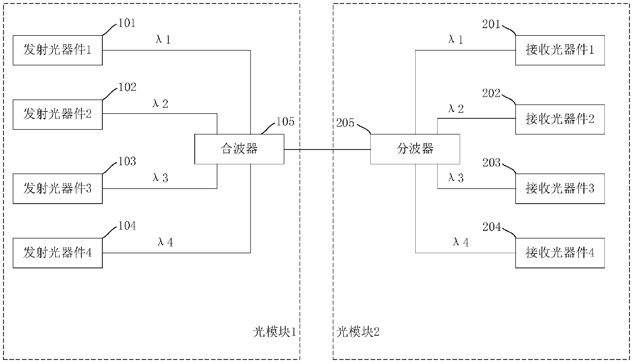
[0047] At present, optical communication with light wave as the carrier has become the main way of global network data communication. In the optical communication industry, the optical module is used to realize photoelectric conversion. Its transmitting optical device (TOSA) converts electrical signals into optical signals through lasers, and transmi


PUM


Abstract

The invention discloses an optical module and a laser wavelength shift adjusting method and device of the optical module, and belongs to the field of optical communication. A wavelength selector allows light of the first wavelength in a first light beam to pass and reflects light not of the first wavelength in the first light beam, and thus, light not of the first wavelength is separated from the first light beam. A processor obtains the optical power of the light not of the first wavelength via a second monitoring detector, obtains the optical power of a second light beam via a first monitoring detector, and obtains the proportion of the light not of the first wavelength in the first light beam according to the optical power of the first light not of the first wavelength and the optical power of the second light beam. The light not of the first wavelength is light of the wavelength shift. According to the proportion, the processor can adjust the temperature of a laser via a temperature controller, and thus overcome the wavelength shift of the laser.

Description


Claims


Application Information

Patent Timeline
Owner HISENSE BROADBAND MULTIMEDIA TECH
Why Eureka
Try Eureka