Solar photovoltaic refrigeration assisted hydrate method carbon capture system

A solar energy and hydrate technology, which is applied to machines, refrigerators, refrigeration and liquefaction using solar energy, can solve the problems of high cost, low efficiency, slow speed, etc., to improve energy utilization, simple process flow, and environmental pollution small effect

Inactive Publication Date: 2016-07-06
TIANJIN UNIV
View PDF8 Cites 1 Cited by
  • Summary
  • Abstract
  • Description
  • Claims
  • Application Information

AI Technical Summary

Benefits of technology

This technology helps reduce emissions from industrial processes by separating out carbon dioxide (CO2) produced during combustion or other chemical reaction steps. It achieves this by combining multiple stages of physical methods together for efficient use of resources like water vapor and gases. Additionally, it reduces harmful greenhouse effect caused by fossil fuels used in these industries due to their high concentration levels of nitrogen oxides released when burning them.

Problems solved by technology

This patented technical describes different methods used to separate hydrogen sulphate compounds like methane into pure form called saturated hydrocite. These techniques involve capturing CO2 released when combustion processes generate excess amounts of nitric acid mist. By combining both chemicals together, efficient removal of harmful substances becomes possible without causing issues associated with traditional systems. Additionally, the use of biomass sources reduces CO2 levels but increases the risk of clogging pipelines due to accumulation over time. Hydrotalcite materials offer advantages including improved selectivity towards specific molecules, reduced power usage compared to other alternatives, lower operational temperatures than current ones, less volatile organics produced per unit volume, higher purity products, and better recycling capabilities.

Method used


Image

  • Solar photovoltaic refrigeration assisted hydrate method carbon capture system
  • Solar photovoltaic refrigeration assisted hydrate method carbon capture system

Examples


Embodiment Construction

[0023] The technical solution of the present invention will be further described in detail below in conjunction with the accompanying drawings and specific embodiments, and the described specific embodiments are only for explaining the present invention, and are not intended to limit the present invention.

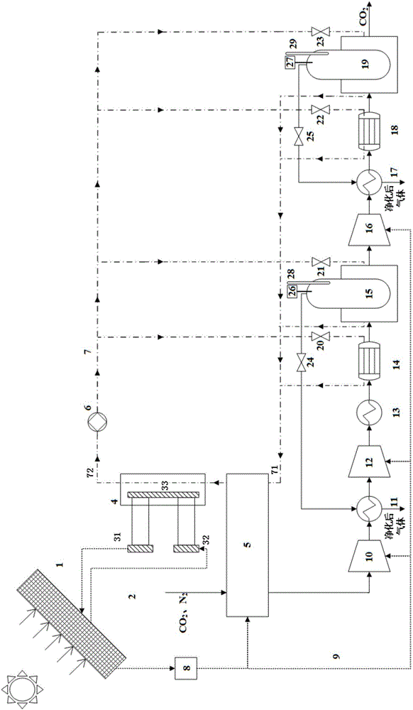
[0024] Such as figure 1 As shown, a solar photoelectric refrigeration assisted hydrate carbon capture system of the present invention includes a solar thermoelectric refrigeration subsystem, a solar power supply voltage control subsystem, a brine circulation subsystem, and a carbon dioxide capture subsystem.

[0025] The carbon dioxide capture subsystem is a two-stage carbon dioxide capture subsystem of the hydrate method;

[0026] The solar thermoelectric refrigeration subsystem includes a thermoelectric refrigeration device connected to one end of the solar power generation device 1. The thermoelectric refrigeration device includes a first hot end 31, a cold end 33 and a se


PUM


Abstract

The invention discloses a solar photovoltaic refrigeration assisted hydrate method carbon capture system. A solar power generation device is connected with a thermoelectricity refrigeration device and an inverter, and the other end of the inverter is connected with an absorption-type refrigerating machine and various levels of compressors; after exchanging heat with the thermoelectricity refrigeration device and the adsorption-type refrigerating machine, a refrigerating medium exchanges heat with various levels of coolers and various levels of reaction kettles; and mixed gas such as industrial smoke CO2, N2 and the like successively passes through the absorption-type refrigerating machine, a primary hydrate method carbon capture system and a secondary hydrate method carbon capture system. By utilizing the solar photovoltaic refrigeration assisted hydrate method carbon capture system, the gradient utilization of energy is realized, the solar power generation is used for providing power to the thermoelectricity refrigerating device, the absorption-type refrigerating machine and various levels of compressors, so as to provide a low-temperature high-pressure environment for generating a hydrate; and by adopting the hydrate two-level separation method, CO2 is captured, the process flow is simple, raw materials are cheap, and the separation efficiency is improved; and the solar power generation system, the thermoelectricity refrigerating system and the hydrate method CO2 capture system are used for separating the industrial gas, so that the pollution to the environment is small, and the energy utilization efficiency is high.

Description


Claims


Application Information

Patent Timeline
Owner TIANJIN UNIV
Why Eureka
Try Eureka